Standard contents -
galvanized steel casing RAL9005 black lacquered steel casing, lower AISI 304 stainless steel condensation drainage canal - non-lacquered -
Economic – non-lacquered Al/Cu heat exchange with bleed valve -
Exclusive – RAL 9005 black lacquered Al/Cu heat exchanger with bleed valve -
aluminium U-frame, silver elox -
metal cover plate -
set of low-energy EC fans 24V DC -
24 V DC terminal block and regulator (FCR BOX) -
levelling set screws and 4 anchors -
spacers for correct installation and concreting -
hardboard cover to protect trench heater from contamination -
durable packaging, installation instructions | Optional accessories - choice of grilles
- Cross grille – design solutions – necessary to order together with trench heater
- light/dark bronze and black elox or RAL colour chart lacquered aluminium U-frame
- silver, light/dark bronze and black el.or RAL colour chart lacquered aluminium F-frame
- lockshield, thermostatic valve or axial thermostatic valve
- ½"×½" 90° brass elbow for connection facilitation
- stainless steel flexible hoses
- thermoelectric actuator TEP 24
- DC power supply 60 W, 100 W, 150 W, 240 W and 480 W
- manual room thermostat SIEMENS RAB 21-DC
- electronic room thermostat with touch LED display HY607LIC
- electronic room termostatwith LCD display SIEMENS RDG 260T or RDG 260KN
- external room temperature sensor QAA32
- R-Box
- sound insulation sheet
- raised floor structural supports
- strengthened OSB cover for installation purposes
|
Suitable grilles
| | Linear aluminium silver | Roll-up aluminium dark bronze | Linear aluminium dark bronze |
| Roll-up aluminium light bronze | Linear aluminium light bronze | Roll-up aluminium black elox - NEWS 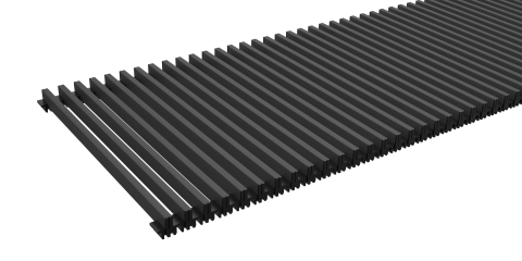 | Linear aluminium black elox - NEWS 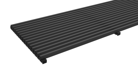 |
| Roll-up steel | Linear steel | Roll-up stainless steel | Linear stainless steel |
Roll-up natural / lacquer beech | Roll-up natural / lacquer oak | Roll-up natural / lacquer mahogany
(upon request) | Cross (upon request) |
FRAMES
| U-frame | F-frame | Cross frame - Lowered
casing edge |
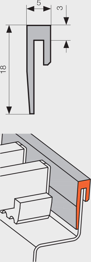 | 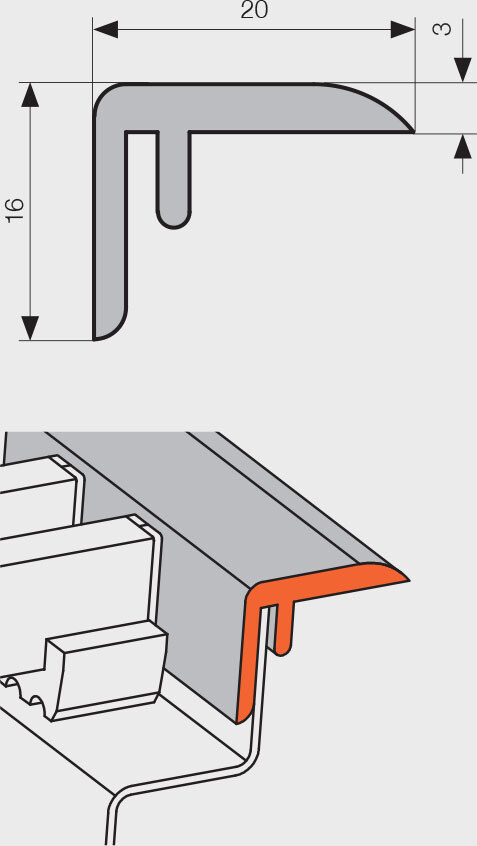 | 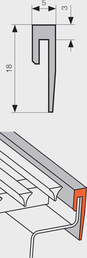 |
Decorative U-shaped and F-shaped frames are available as standard in aluminium with silver, black, dark bronze or light bronze elox finishes. U-frame and Cross frames are available also in black elox. Frames may also be lacquered (powder coated) using colours from the RAL colour chart. Frames are in every case supplied as a component of trench heaters, and the type required must be specified when ordering in the Order Code.
FV TRENCH HEATER INSTALLATION
Construction recommendations
To ensure correct operation, it is essential that the following principles are respected.
-
Trench heaters must be installed horizontally with the heat exchanger on the window side. For the grille to function correctly, the upper edge of the casing must be straight and level (not buckled or bent).
-
The maximum recommended distance of the trench heater from the wall/window is 100 mm.
-
The size of the trough in the floor for the trench heater installation should be at least 100 mm bigger (both in length and width) than the convector.
-
We recommend connecting the trench heater to the heating system using a lockshield and thermostatic valve. The heat exchanger connection is by an inner G½ thread. Following connection to the heating system, bleed and carry out a pressure test.
-
When concreting, the trench heater must be levelled using the set screws provided and fastened to the floor using the anchors provided. The anchors keep the trench heater in place while pouring concrete.
-
While pouring concrete, the trench heater may be weighed down.
-
Using anchors will extend the bottom width of the trench heater by 42 mm from each side.
-
While pouring concrete it is important to brace the trench heater to prevent longitudinal buckling. Trench heaters are fitted with spacers for this purpose. Following concreting, these spacers are easily removed. Note: FVP models as standard are, however, not equipped with spacers.
-
While pouring concrete or anhydrite it is essential to seal all connection openings to prevent leakage. We also recommend insulating trench heaters against dampness.
-
Where trench heaters are not concreted in, raised floor supports are recommended to use. Standard models are not self-supporting.
-
We recommend insulating the outer side of the trench heater casing along the length of the heat exchanger with polystyrene to prevent heat loss into the floor.
-
For trench heaters with forced convection we recommend undertaking fastening and acoustic insulation by pouring thin concrete along the sides and under the base of the heater.
-
To avoid contaminating the trench heater, we recommend maintaining the protective hardboard cover in place during construction work. The cover, which is included in the standard contents, is not suitable for walking on and serves solely to protect the trench heater from contamination during installation. Strengthened OSB covers for installation purposes are available as optional extras.
-
Fans are attached to the trench heater casing using magnets. For stainless steel models velcro is used. This system enables the removal of the fans from the trench heater during installation to avoid damage or contamination, etc. Fans may also be removed this way for cleaning when the unit is switched off. With the exception of the Pool series, fans are installed to direct air towards the windows.
-
Electrical installation design must be carried out by suitably qualified persons in accordance with the relevant regulations.
-
Installation and servicing of the electrical installation must be carried out by persons with the relevant electro-technical qualifications.
-
Prior to commissioning, the electrical components must be thoroughly inspected in accordance with relevant regulations.
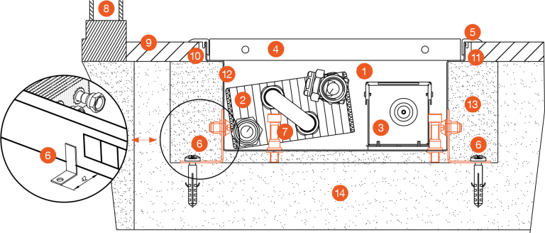
1- trench heater with forced convection, 2 - heat exchanger, 3 - fan, 4 - grille, 5 - F-frame,
6 - anchors, 7 - set screws, 8 - window, 9 - floor level, 10 - grout, 11 - expansion joint,
12 - insulation, 13 - concrete, 14 - sub-floor
Raised floor installations
Structural supports for raised floor trench heater installations offer stable and effective solutions. Structural supports are manufactured from non-lacquered steel and are suitable for raised floors of a depth of up to 500mm. Structural supports are suitable for Optimal-V, Energy, Variant F2V and F4V. For structural reasons, the KORAFLEX Pool-V model is not recommended for installation into raised floors.
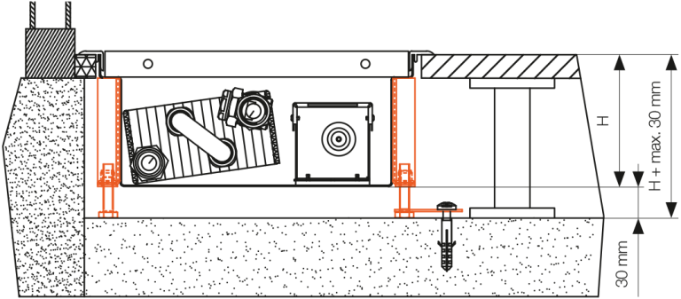 SZP-03 low-raised floor support
Trench heaters are fitted with reinforcing bars and set screws, which enable the trench heater to be installed at the required height. Set screws must be anchored to the floor to prevent movement. Reinforcing bars are not included as standard and cannot be fitted subsequently. The screws allow setting a maximum height which is max. 30 mm higher than the trench heater itself. Recommended for raised floors with a maximum depth 30 mm greater than the unit height of the trench heater.
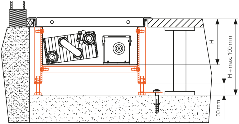 SZP-10 higher raised floor support
Customized solutions for all projects dealing with raised flooring. This is a more robust model of the low raised floor support, equipped with one support at the base of the trench heater. The precise technical design depends on customer's requirements. Recommended for raised floors with a maximum depth 100 mm greater than the unit height of the trench heater.
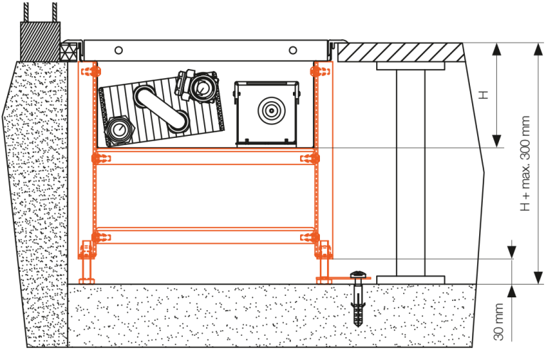 SZP-30 high-raised floor support
Customized solutions for projects dealing with high raised flooring. This is a more robust model of the higher raised floor support, equipped with two supports at the base of the trench heater. The precise technical design depends on customer's requirements. Recommended for raised floors with a maximum depth 300 mm greater than the unit height of the trench heater.
TRENCH HEATER MULTIPLE INSTALLATIONS
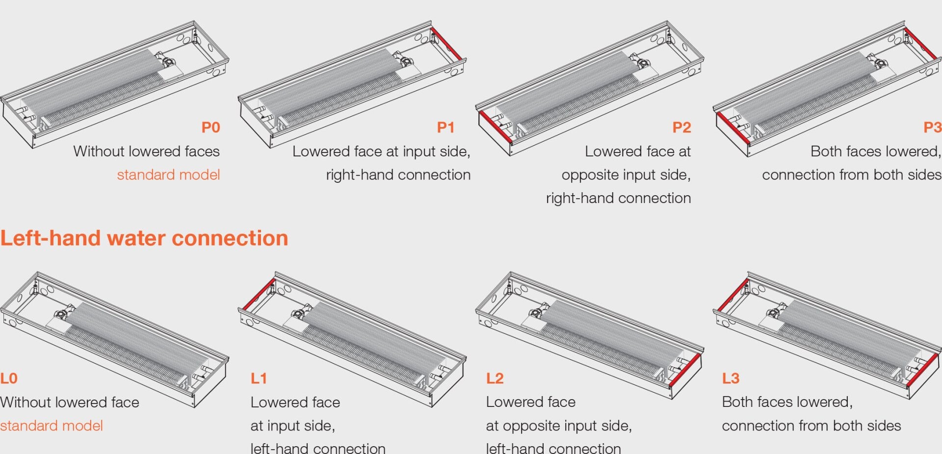
Casing types according to water connections and lowered faces for multiple installations
Lowered trench heater casing faces are used where invisible connections are desired between convectors (multiple convectors around a room, eg. in administrative buildings, restaurants, hotels, etc.). When ordering grilles, care must be taken to include information in the order code that the grilles required are to be used with trench heaters with lowered faces.
NUMBER OF FANS PER TRENCH HEATER 
|
.png)