Standard contents hot-dip galvanized steel casing, non-lacquered non-lacquered Al/Cu heat exchanger with bleed valve aluminium U-frame, silver elox metal cover plate levelling set screws and 4 anchors spacers for correct installation and concreting hardboard cover to protect trench heater from contamination durable packaging, installation instructions | Optional accessories cover grille of your choice
Cross or Robust cover grille – project solution – necessary to order together with trench heater
(includes a casing construction modification)
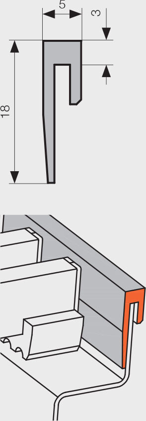
U-frame in aluminium, available in black elox, light / dark bronze elox or lacquered according to the RAL colour chart
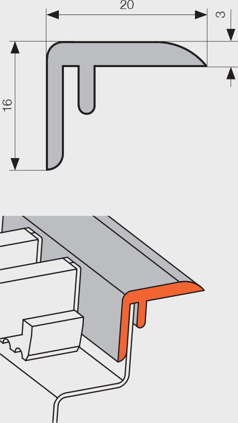
F-frame in aluminium, available in silver elox, black elox, light / dark bronze elox or lacquered
according to the RAL colour chart
supports for raised floors
regulating valve set, angle or straight
thermostatic valve, angle, straight or axial
thermostatic pressure-independent valve, angle, straight or axial
brass elbow ½" × ½" 90°
stainless steel flexible hoses
thermoelectric actuator TEP 230 or TEP 24
SIEMENS thermostat RAA21 or RDE 100.1
thermostatic head with capillary tube
24 V DC power supply unit
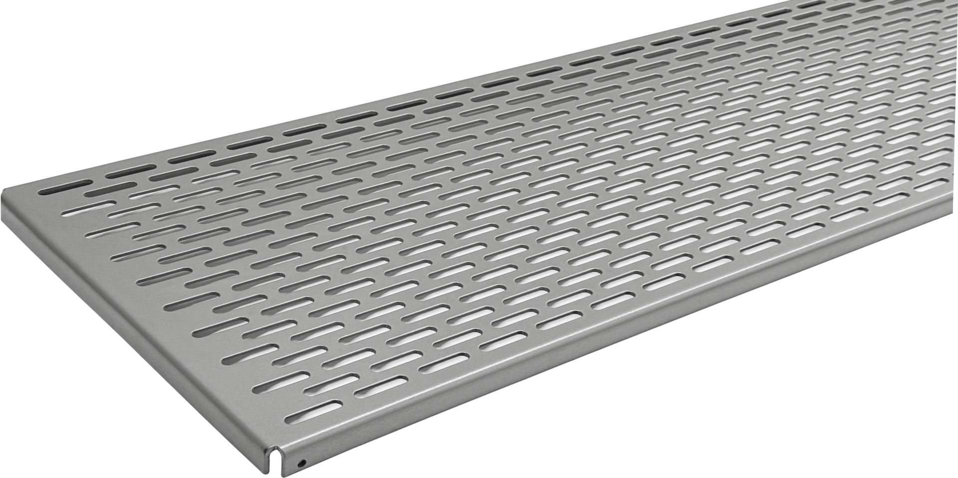
OSB cover board with increased stiffness for installation purposes |
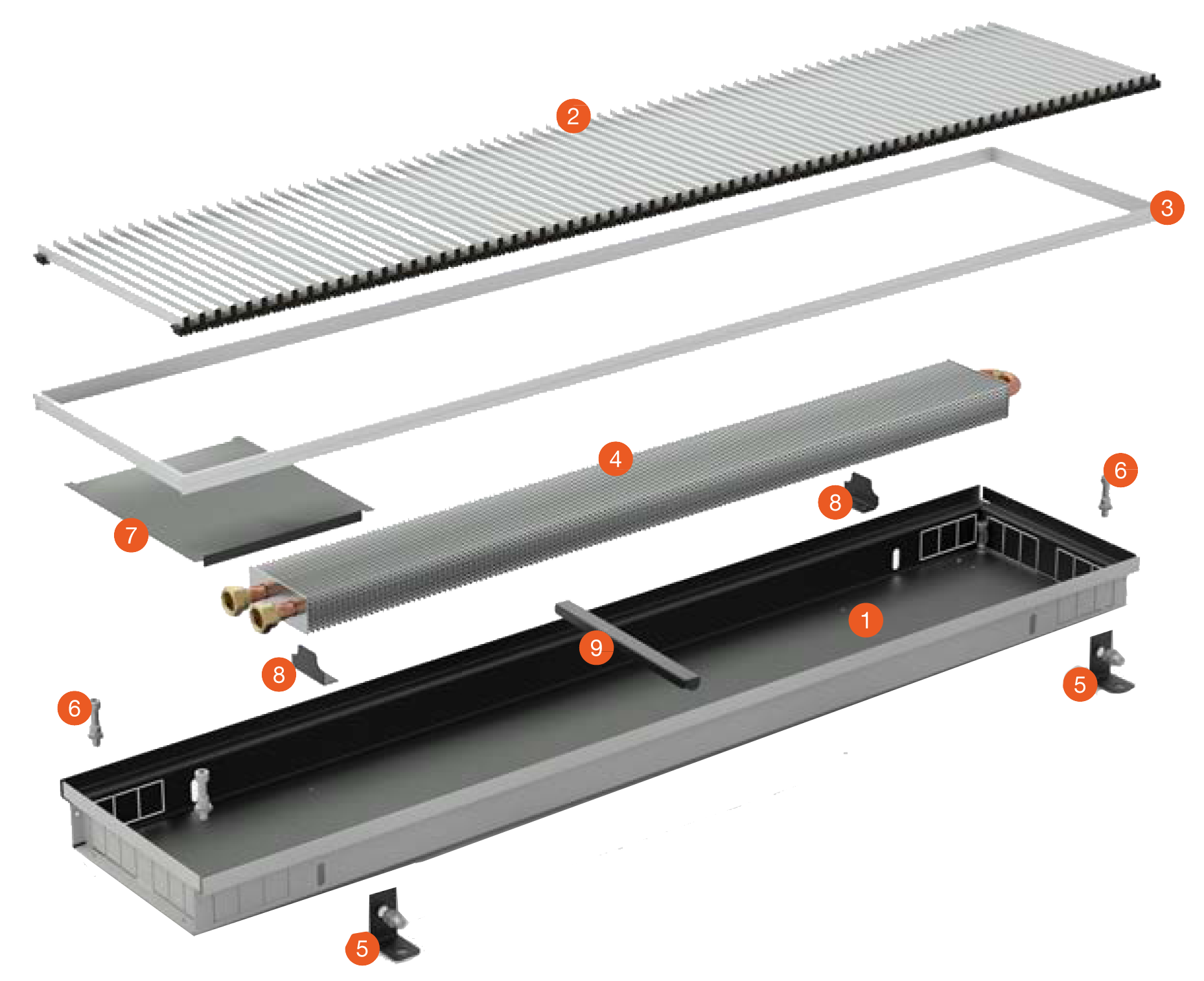
TRENCH HEATER COMPONENTS
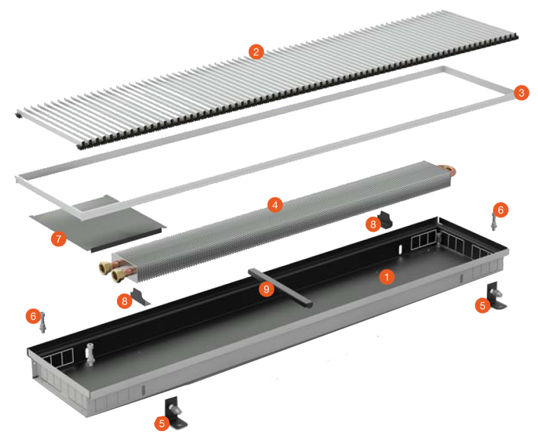 | 1hot-dip galvanized steel casing, non-lacquered 2choice of grille (please order separately) 3choice of aluminium frame 4Al/Cu heat exchanger 54 anchors 6levelling set screws 7metal cover plate 8brackets 9spacers for correct installation and concretin |
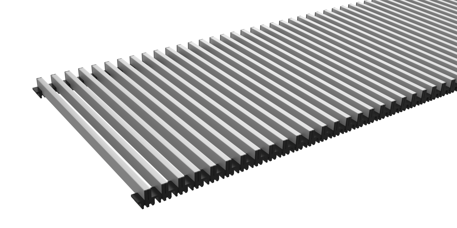
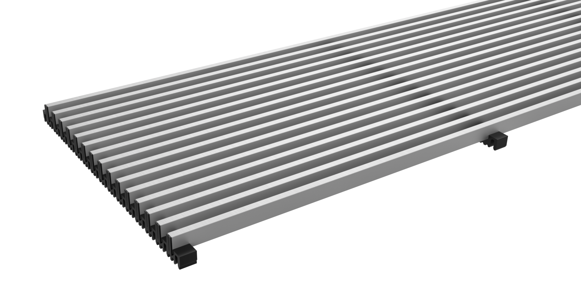
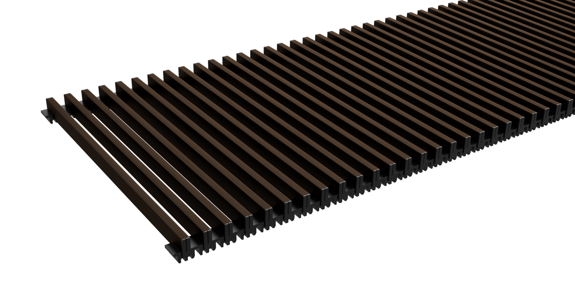
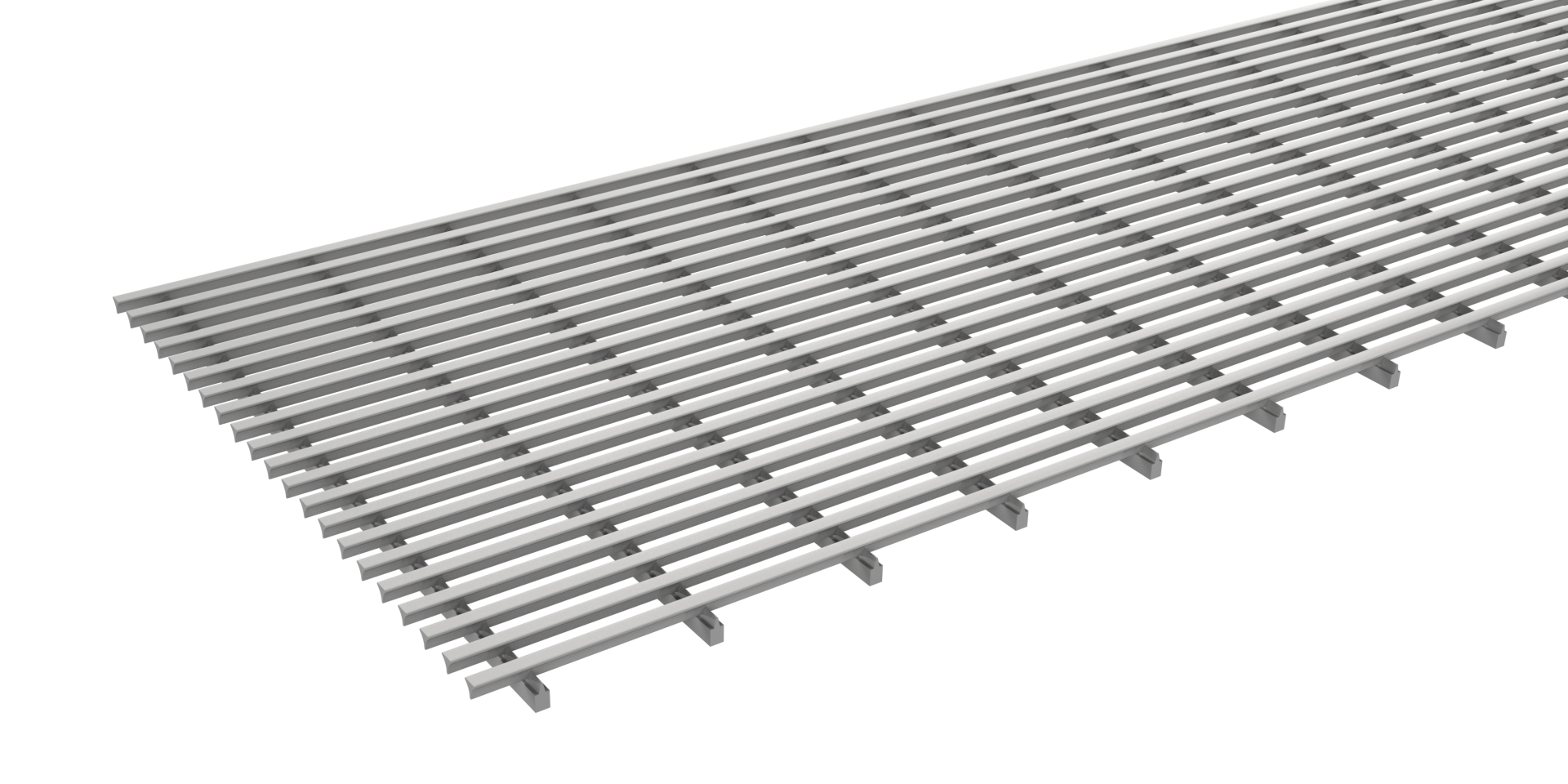
Suitable grilles
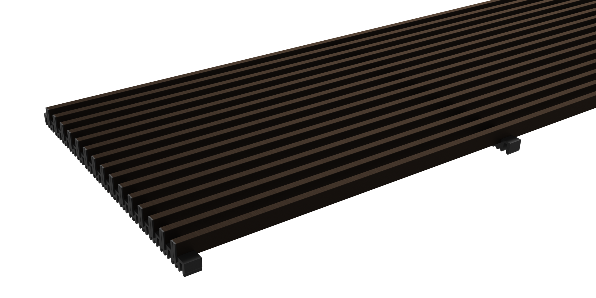
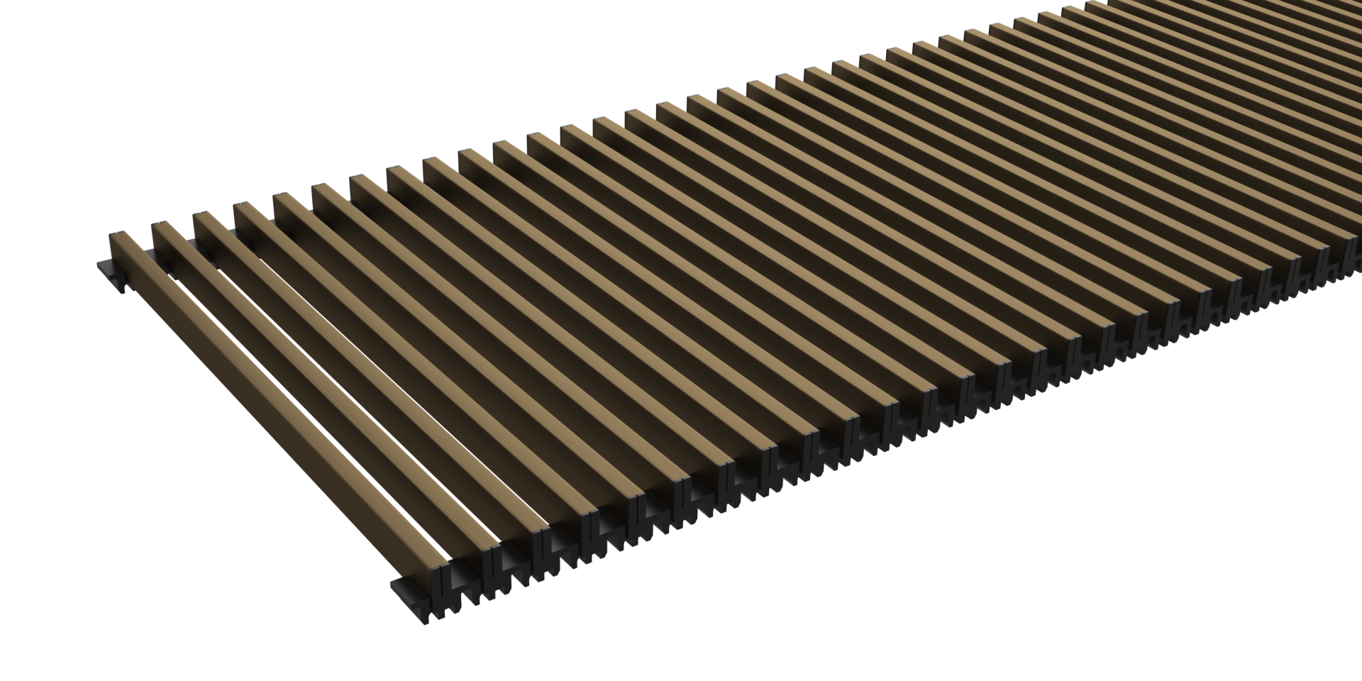
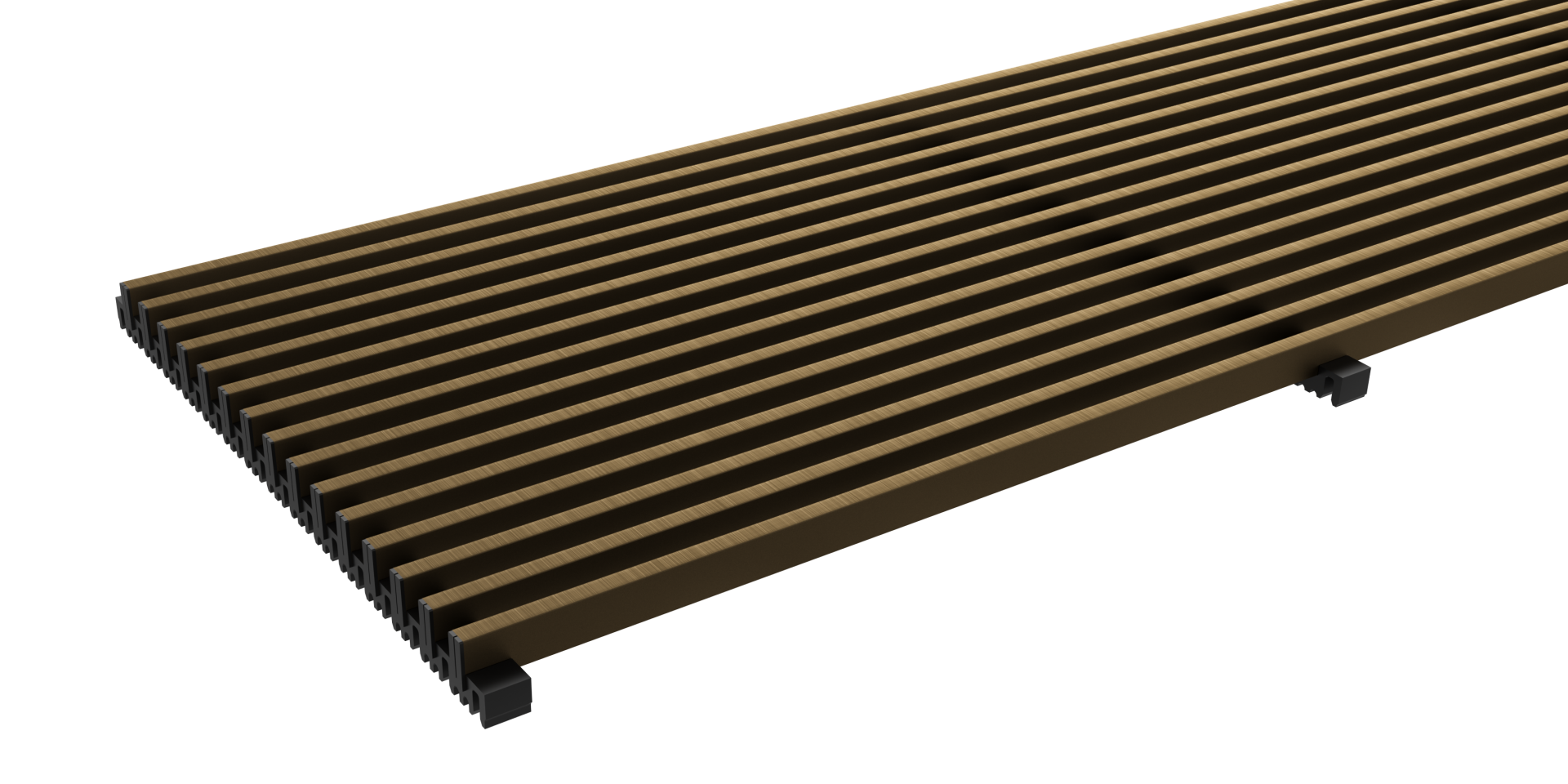
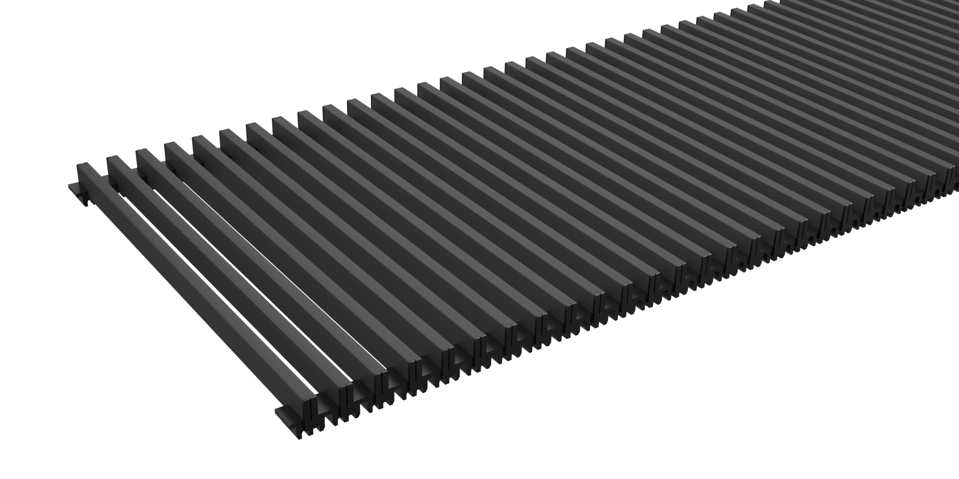
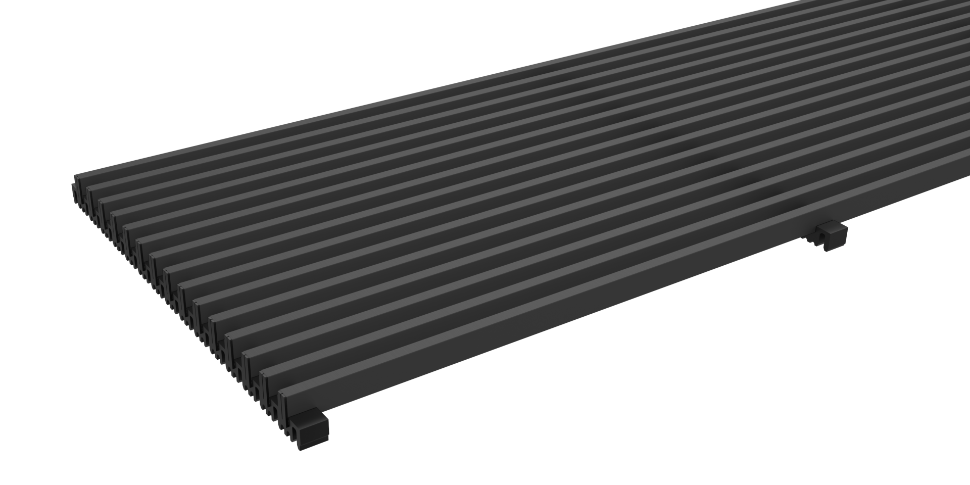
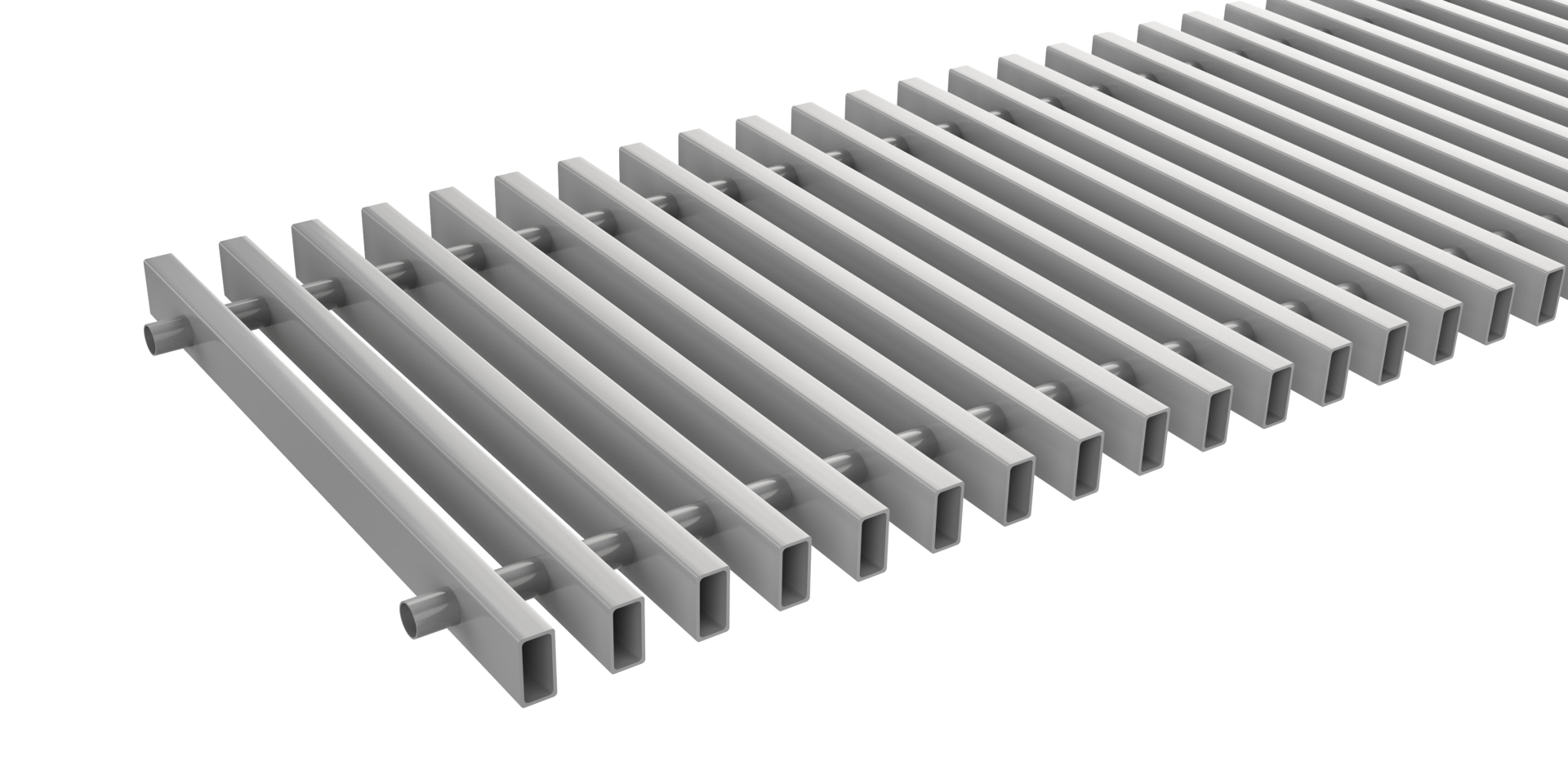
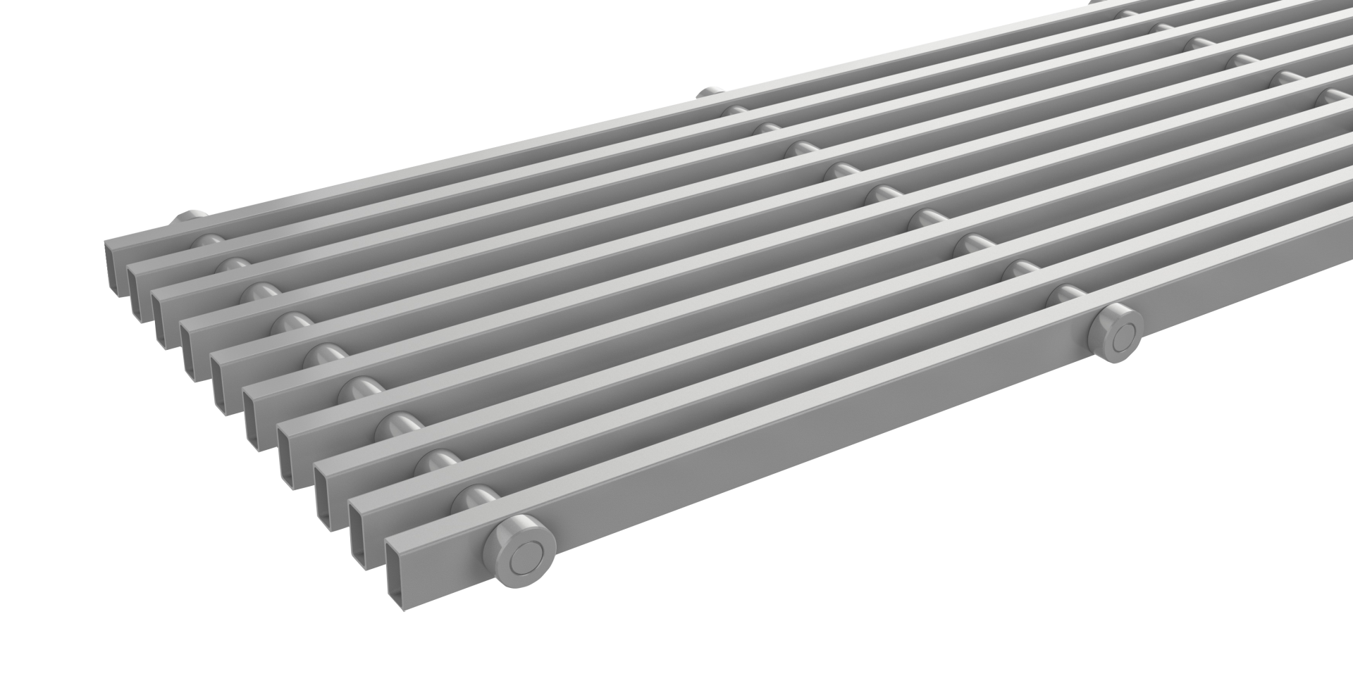
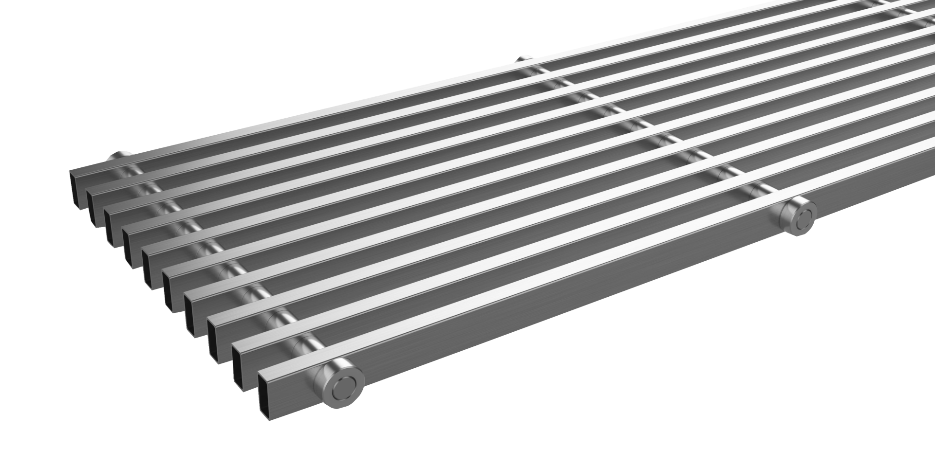
| Roll-up aluminium silver | Linear aluminium silver | Roll-up aluminium dark bronze | Linear aluminium dark bronz |
Roll-up aluminium light bronze 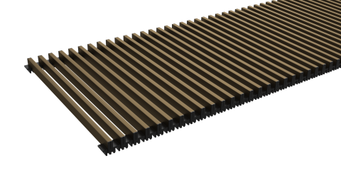 | Linear aluminium light bronze 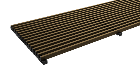 | Roll-up aluminium black elox 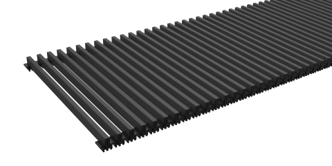 | Linear aluminium black elox 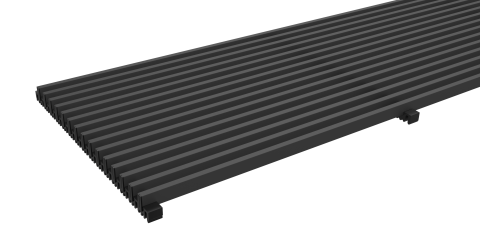 |
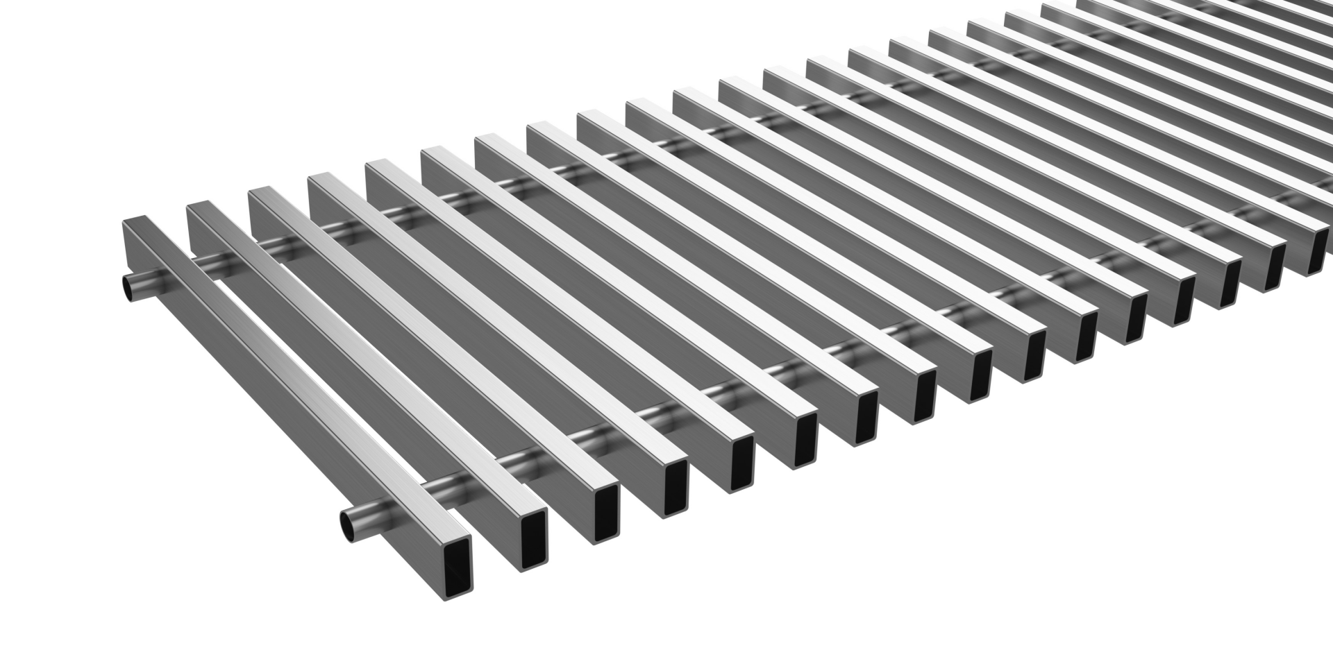
| | Linear steel 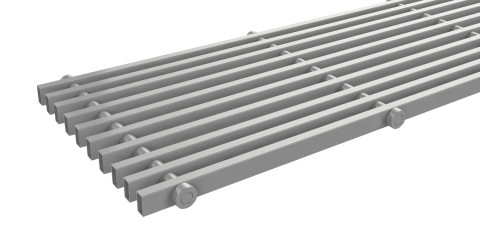 | Roll-up stainless steel 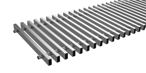 | Linear stainless steel |
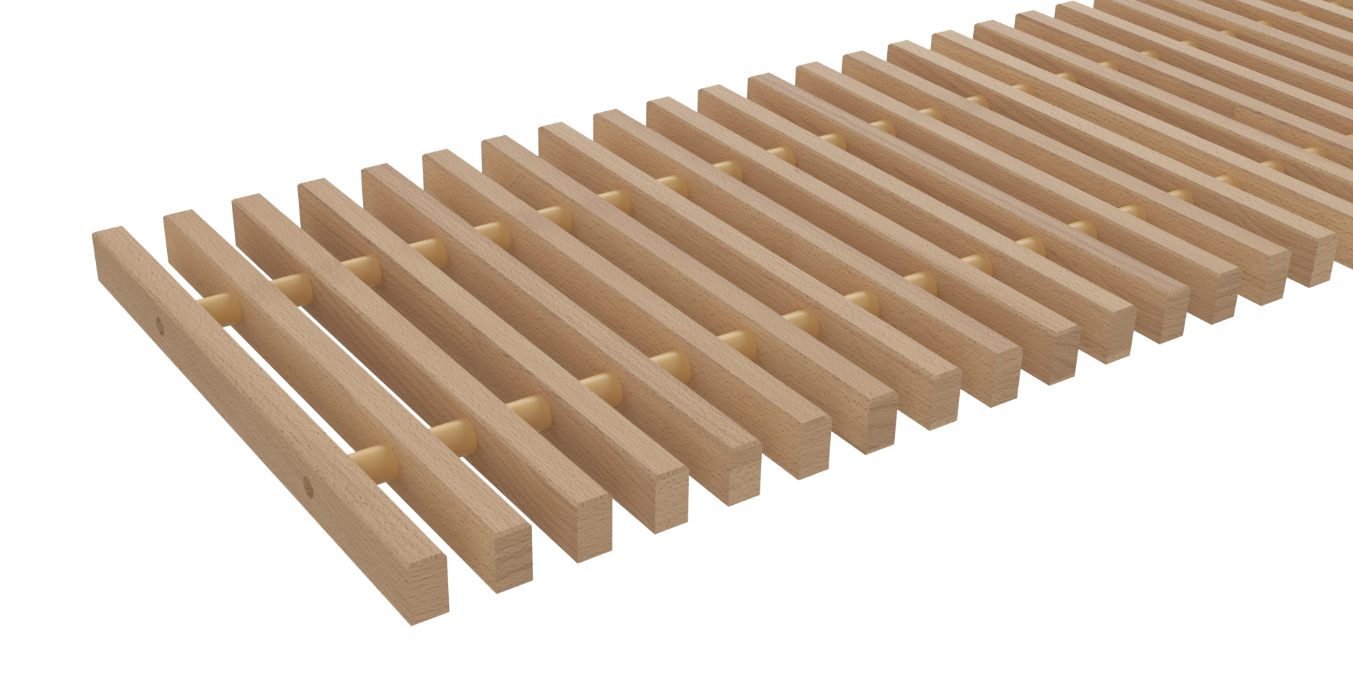
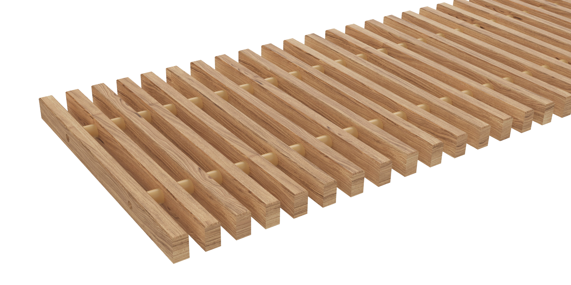
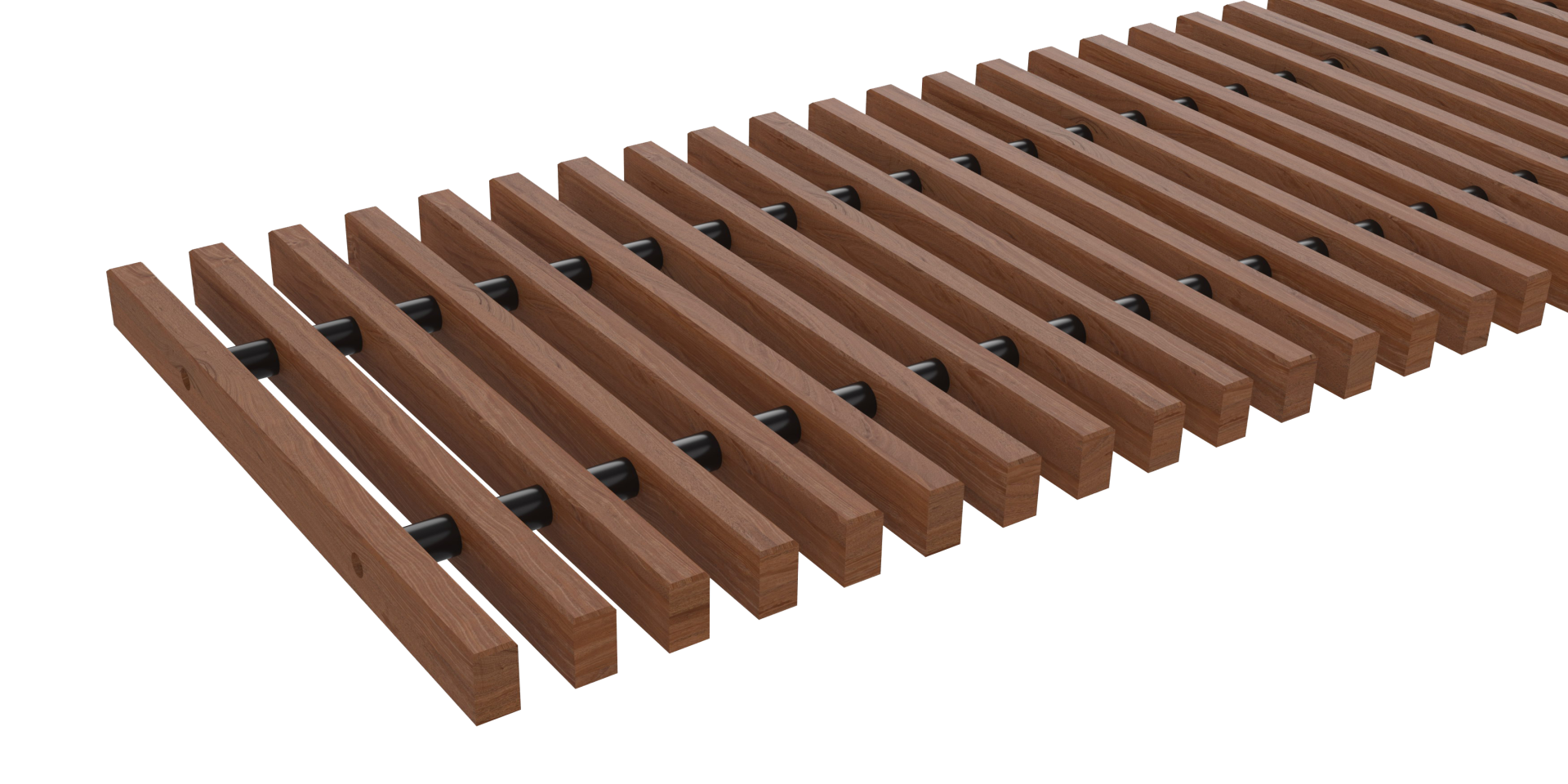
Roll-up natural/lacquer beech 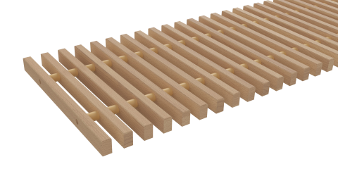 | Roll-up natural/lacquer oak | Roll-up natural/lacquer mahogany (upon request) 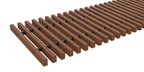 |
Cross (upon request)
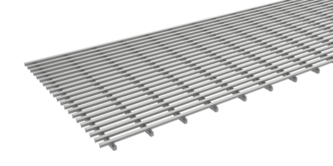 | Robust steel/stainless steel (upon request)
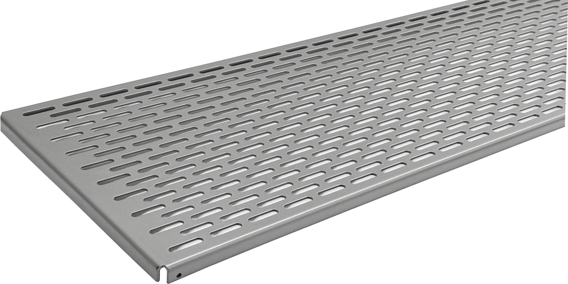 | | |
Frames
| U-frame | F-frame | Cross frame – Lowered
casing edge |
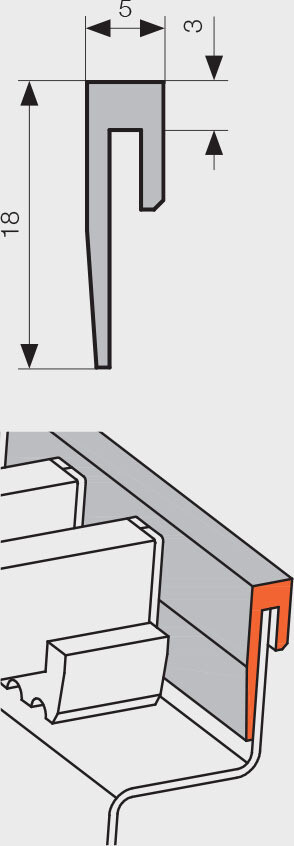 | 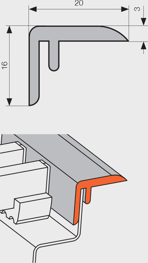 | 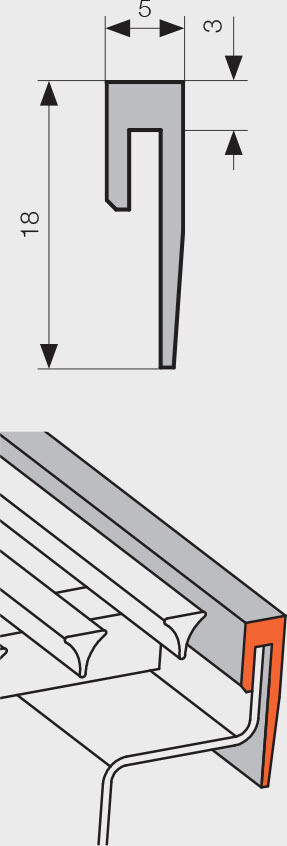 |
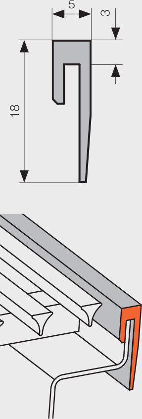
 Decorative U-shaped and F-shaped frames are available as standard in aluminium with silver, black, dark bronze or light bronze elox finishes. U-frame and Cross frames are available also in black elox. Frames may also be lacquered (powder coated) using colours from the RAL colour chart. Frames are in every case supplied as a component of trench heaters, and the type required must be specified when ordering in the Order Code.
FK TRENCH HEATER INSTALLATION
Construction recommendations
To ensure correct operation, it is essential that the following principles are respected.
A properly installed trench heater must be positioned horizontally, with the heat exchanger oriented towards the window. The trench heater casing must have straight, non-deformed upper edges to ensure correct operation of the cover grille.
Installation of the trench heater is possible
• in a concrete floor (standard construction solution)
• in a plinth – for renovations or additional modifications
• in raised floors – using special supports designed for this purpose - For KORAFLEX Pool (FKP, FVP) installation of raised floor supports is not recommended for design reasons.
In all cases, it is necessary to anchor the trench heater firmly to prevent it from being stepped on and to ensure that all technical installation requirements are met. We recommend leaving the cover plate in place throughout the construction work to prevent contamination of the trench heater’s internal space. A non-walkable hardboard cover is supplied as
standard for basic protection. For installation purposes, an OSB cover with increased rigidity can be ordered as an optional accessory.
- The recommended installation distance of the trench heater from the window / wall is max. 100 mm.
- The installation opening should be at least 100 mm larger than the convector dimensions in both length and width.
- For trench heaters with natural convection (without fan), for lefthand connection to the heating system it is sufficient to rotate the heat exchanger by 180°.
- When using fixing anchors, the bottom width of the trench heater is increased by 42 mm on each side.
- During concreting, the trench heater must be levelled horizontally using the levelling set screws and fixed using fixing anchors, which prevents the trench heater from shifting during subsequent concrete pouring.
- We recommend connecting to the heating system using a lockshield and a thermostatic valve. The connection to the heat exchanger is an inner thread G ½". After connection to the heating system, bleed the trench heater and carry out a pressure test.
- We recommend thermally insulating the trench heater before installation on the outer longer sides of the casing (e.g. polystyrene) to prevent heat losses into the floor.
- For trench heaters with a fan, we recommend fixing and sound insulation by pouring lean concrete along the sides and under the bottom of the casing.
- During concrete pouring, the trench heater must be loaded vertically.
- During concreting, it is very important to brace the trench heater to prevent longitudinal bending. For this purpose, spacers are installed in the trench heater. After concreting, these spacers can be easily removed.
- During concrete or anhydrite pouring, thoroughly seal all openings into the trench heater to prevent it from being filled with building material. We also recommend insulating the trench heater casing against moisture.
- If the trench heater will not be concreted in, we recommend using one of the raised floor installation variants. The standard version of the trench heater is not self-supporting.
- KORAFLEX Variant F2V and F4V trench heaters with cooling and Pool versions (FKP, FVP) for humid environments are equipped as standard with a built-in condensate or overflow water drain. The F2V 11/20 variant and the Pool version have a drain tube positioned towards the wall. During installation of all the above-mentioned types, it is necessary to connect the tube at the bottom of the trench heater to piping with a secured slope for the drainage of overflow water or condensate. We recommend fitting the drain with an odour trap.
- The fans are attached to the trench heater casing using magnets. In the stainless steel version, the fans are attached with hook-and-loop fasteners. This system allows the fans to be removed from the trench heater during installation to prevent damage or contamination. During normal operation, they can also be removed in the switched-off state and cleaned. In all model lines except the Pool line, the fans are installed so that the airflow is directed straight towards the window.
- KORAFLEX Pool (FKP, FVP) trench heaters are designed for use near swimming pools. The separation partition serves to collect water from the pool, but cannot function as a standard pool overflow. This part is always positioned closer to the pool. The heating section with the heat exchanger and fans must always be positioned further from the pool. KORAFLEX Pool is equipped with two drain tubes. Installation, operation and maintenance of these units require special conditions, which can be found on our website or in the installation instructions. Not suitable for saltwater pools.
- The electrical installation design must be carried out by a person with the appropriate professional qualifications and must comply with the relevant standards.
- Installation and servicing of the electrical system must be performed by a qualified person with the appropriate electrotechnical qualifications.
- Before commissioning, an initial inspection of the electrical installation must be carried out in accordance with the applicable standards.
Recommended positioning of heat exchangers in trench heaters
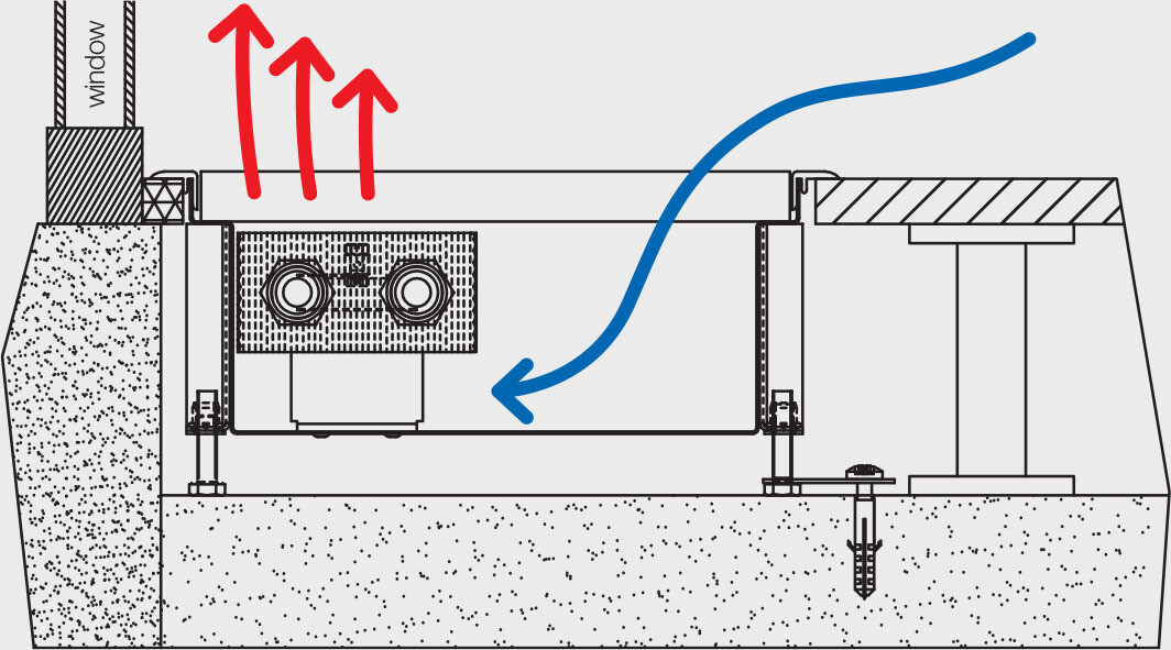
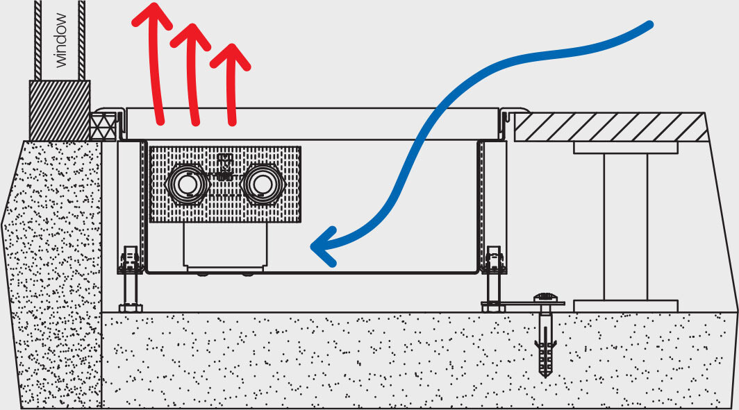
• Trench heaters should be positioned a maximum of 100 mm from windows. In order to achieve maximum performance, the recommended position for heat exchangers in the trench heater is always on the window side. This results in natural air flow, whereby warm air rises and cool air is drawn into the trench heater. In this way, cool air at the window is screened and the air in the room is heated.
TRENCH HEATER INSTALLATION
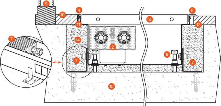
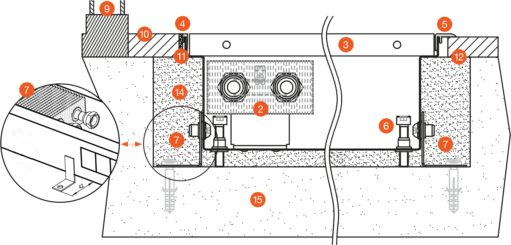
1 - trench heater with natural convection, 2 - heat exchanger, 3 - grille, 4 - U-frame, 5 - F-frame, 6 - set screws, 7 - anchors, 8 - up to 300mm deep dividing partition, 9 - window, 10 - floor level, 11 - grout,
12 - expansion joint, 13 - insulation, 14 - concrete filler, 15 - sub-floor
Raised floor installations
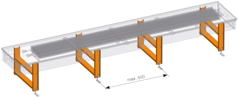
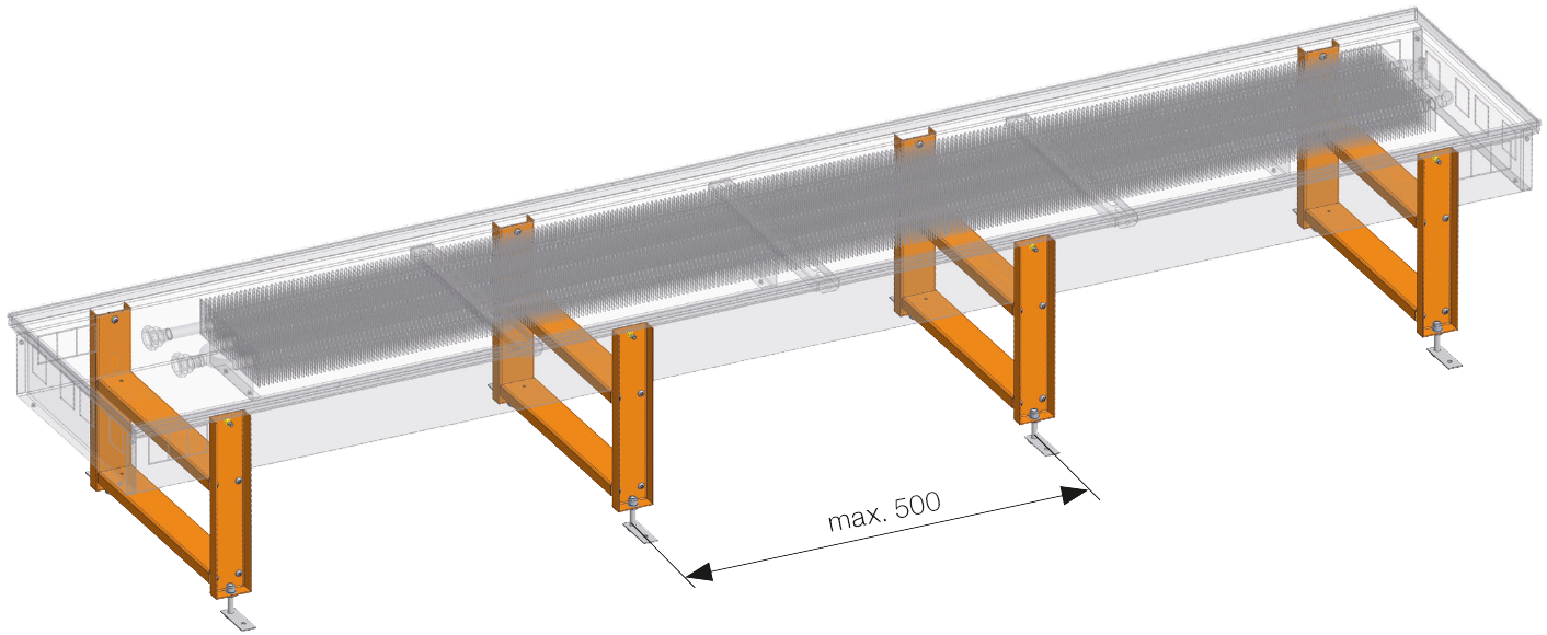
• Structural supports for raised floor trench heater installations offer stable and effective solutions. Structural supports are manufactured from non-lacquered steel and are suitable for raised floors of a depth of up to 500 mm. Structural supports are suitable for
Optimal FKO and
Basic FKB models.
Supports must be ordered together with trench heaters due to structural alterations to convector casings! Components of several types of raised floor support are integral parts of the trench heater body.
Trench heater multiple installations
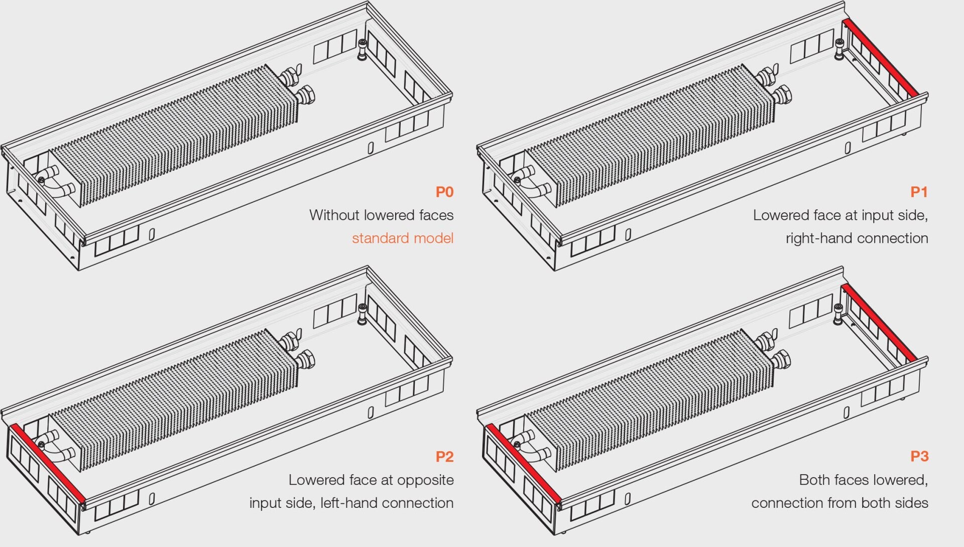
Casing types according to water connections and lowered sides for multiple installations
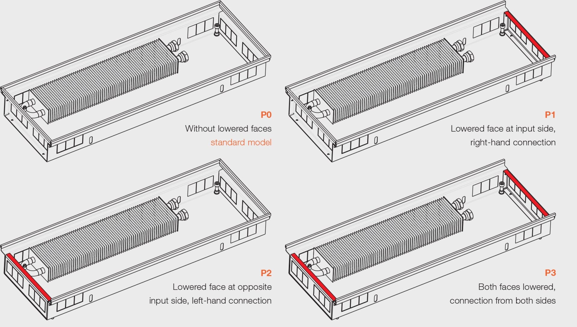
• Lowered trench heater casing sides are used where invisible connections are desired between trench heaters (multiple trench heaters around a room, eg. in administrative buildings, restaurants, hotels, etc.). When ordering grilles, care must be taken to include information in the order code that the grilles required are to be used with trench heaters with lowered faces.
 Heating
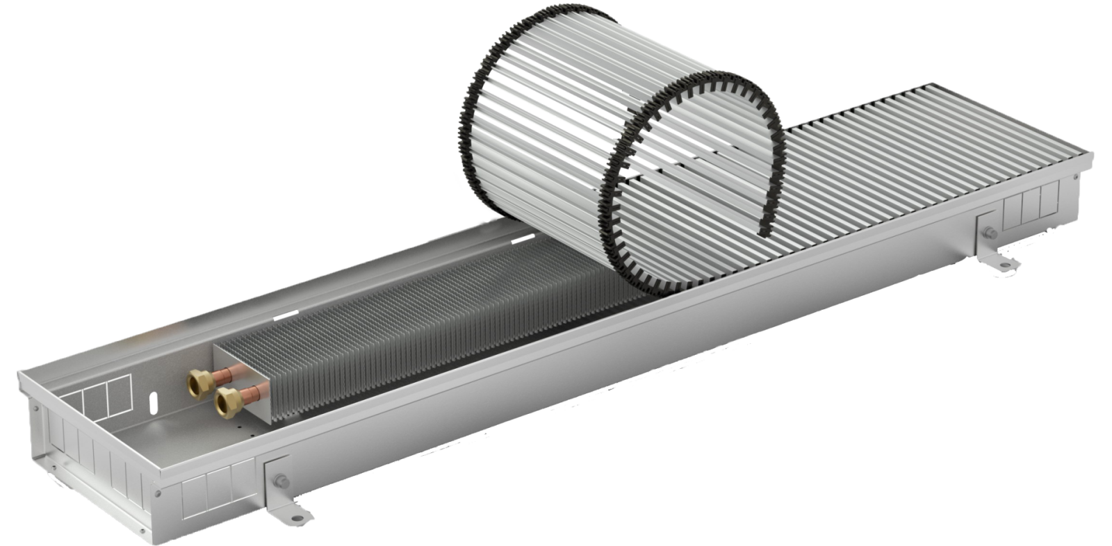
 Natural convection
 Low energy consumption