It seems that you are using a browser that does not support today's standard for displaying web content. This may cause some parts of the website to not function properly. We recommend that you update your browser or download one that meets today's standard.

Update

Cookie settings

Cookies are small browser files that allow us to temporarily store information about your device and you, as a user, exclusively while you are browsing the LICON website. These files help us obtain information about traffic and user behavior, based on which we continuously improve the website.

Back to list

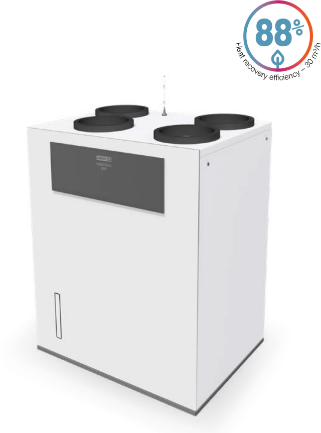
VENTBOX 800

Public buildings and family houses up to 600 m²

The VENTBOX 800 central heat recovery unit provides controlled ventilation with air recovery and also serves as an effective tool for perfect filtration and removal of dust and various allergens from fresh incoming air. The heat recuperation unit also contributes to improvement of the building thermal performance. The use of sensors makes it possible to effectively ventilate radon, control CO2 levels, or remove excessive moisture building in the house. This version is one of the
most efficient ventilators on the market with the A+ energy class.

  • Premium Version
    The unit is equipped with unique EC motors with constant flow function. These unique motors compensate for pressure losses when the supply air flow is reduced, e.g. when the air filters become clogged. With these premium EC motors, the unit can operate more efficiently and economically; which positively affects the overall dynamics and also the economy of the heat recovery system use. The unit is provided with frost protection, and performance setting according to the current need and temperature. The unit is also equipped with an automatic by-pass function, where it compares the temperature of the indoor and outdoor air and switches on the bypass damper as required. This prevents the outdoor air from being heated by the exhaust air. The heat recovery unit can also be remotely controlled and operated via a web interface from a computer, smartphone, or tablet connected to the local network in the house.
  • Fresh air without allergens and pollen
  • Possibility of intensive extraction
  • Radon-free house
Recommended area up to 600 m²
Energy class A+
Installation option Floor mounting, wall mounting  right variant
Dimensions (h × w × d) 1270 x 1005 x 740 mm
Weight [kg]  112 kg 
Voltage 230 V AC/50 Hz
Electric current without preheating [A] 1.5 A
Electric current including preheating [A] 12 A
Max. input power of the unit without preheating [W] 318 W
Max. preheating input power [W] 2 550 W
Total power consumption [W] 2 868 W
IP coverage 30
Air flow [m³/h] 120–800 m³/h
Maximum airflow in BOOST setting [m³/h] 800 m³/h
Reference air flow [m³/h] 560 m³/h
Displacement pressure [Pa] 50–200 Pa
Acoustic energy LWA [m³/h/Pa/dB] 560 m³/h/50 Pa/49 dB
Heat transfer efficiency / Flow rate 82 %/800 m³/h; 82 %/560 m³/h; 81 %/120 m³/h
Electrical input (without preheating) 240 W/800 m³/h; 105 W/560 m³/h; 20 W/120 m³/h
∅ of the connection necks [mm] 250 mm
Type of pipe for condensate drainage HT DN 32 mm
Specific power consumption SPI* W/m³/h 0,19 W/at reference airflow 560 m³/h and disposition pressure of 50 Pa
Max. number of all sensors (CO2 / RH / RADON …) 9
Connector for fire sensor or EPS connection Yes
Automatic frost protection Yes
Bypass function (exchanger bypass) Yes
Shock ventilation Yes
Weekly time mode Yes
Measuring energy consumption Yes
Modbus TCP/IP communication Yes
Modbus RTU communication Yes
Analogue input 2
Digital input 1
EC motors with a constant flow function Yes
Filter clogging indicator based on time interval Yes
Wire pre-filter Yes
Filter clogging indicator based on filter pressure drop Yes
Filters supply//exhaust (% of particles captured in a given filter class)  F7 pollen/odour ePM1 70 %   (F7 odour optional)  
By default, the unit is supplied with a counterflow heat exchanger (HRV)    

Enthalpy Counterflow Heat Exchanger (ERV)

Enthalpy counter-flow plate heat exchanger (ERV) is an optional part of the heat recovery system which, in addition to heat recovery, also allows moisture recovery, thus supporting the maintenance of optimal indoor air humidity and thus improving the user comfort of apartments and residential buildings. These systems bring many benefits, including energy efficiency, reduced heating costs, and improved indoor air quality.
Working principle of the counterflow exchanger

EN_800_Entalp


The enthalpy heat exchanger can be ordered separately or later; after a very simple installation, the entire unit is upgraded with advanced technology.
Ordering code: VENTBOX 800:   P-029 

Main features and benefits
• Heat exchange – an enthalpy heat exchanger allows heat energy to be transferred from warmer exhaust air to cooler outdoor air, thereby increasing the temperature of the air entering the building in winter. This helps to reduce heating costs because the fresh air is heated passively during the exchange.

• Moisture exchange – in addition to heat, the enthalpy heat exchanger allows moisture transfer. This is important for maintaining optimum humidity indoors. The moisture in the exhaust air is transferred to the supply air, which can be useful in areas with extreme climatic conditions.

• Reduction of losses and pollution – the enthalpy heat exchanger also serves to separate the supply and extract air, preventing the transfer of pollution, dirt and unwanted odours from the outside into the building. This improves the indoor air quality.
 
• Energy savings – operation without the need to preheat the incoming air down to -5 °C.
Specifications with enthalpy exchanger VENTBOX 800, Premium Version
Energy class enthalpy heat exchanger  A
Weight of the entire unit 106,5 kg 
Heat transfer efficiency / Flow rate 76 %/800 m³/h
78 %/560 m³/h
84 %/120 m³/h
Moisture transfer efficiency / Flow rate 56 %/800 m³/h
63 %/560 m³/h
78 %/120 m³/h

VENTBOX COMPONENTS, FILTERS, CONTROL, BY-PASS

VENTBOX components  
VB_800_rozpad
Basic specifications
 1 the unit‘s enclosure is made of durable material with thermal insulation properties and a compact enclosure
2 front service plate
3 fan service door
4 acoustic panels
5 fans with efficient EC motors
6 fan covers
7 unit suspension system
8 heat exchanger cover HRV
9 heat exchanger cover
10 external Wi-Fi antenna
11 cable route cover
12 air duct sockets
13 control and information panel
14 fuse case with fuse
15 control panel – analogue and digital inputs
16external Wi-Fi antenna terminal
 
17design front cover
18 air purification filters
19 filter closing caps
20 dry rap – condensate drain outlet at the bottom of the unit with 5/4“ connection thread
21 height-adjustable legs
22 adjustable travel
 filter clogging indicator based on time interval
air preheating (3 PTC cells)
filter clogging indicator based on time interval
filter clogging indicator based on filter pressure drop
separate temperature sensor for monitoring the preheating function
temperature sensors for monitoring the air temperature at the outlets and inlets of
the ventilation unit
connector for connecting fire sensor or electrical fire alarm system (EFS)
power cord 230 V AC / 16 A
energy label, package leaflet
assembly and installation instructions, assembly template
Basic Software Functions
• automatic frost protection
•  display of the current preheating performance
•  automatic bypass function (exchanger bypass)
•  manual by-pass control (in summer mode)
•  optional manual defrosting of the heat exchanger (in winter mode)
•  optional connection of a fire sensor or electric fire alarm system (EFS)
• user configurable connected sensors (CO2, relative humidity, total volatile concentration)
•  Modbus communication with a higher-level system (e.g. LOXONE)
• communication with Modbus RTU sensors
•  control including ventilation performance via local network web
 • application interface
•  weekly time mode
•  leaving the premises / holiday function
•  indicative information on current electricity consumption
•  BOOST shock ventilation
•  language versions CZ, EN, DE, FR
Optional Specification
• enthalpy counter-flow plate heat exchanger ERV 
• vontinuous manual P.R.T. control with wall-mounted remote controller 
• CO2 concentration sensor
• relative humidity (RH) sensor
• radon concentration sensor
• combined TVOC and HCHO (volatile substances and formaldehyde) sensor
• carbon odour filters INPUT F7 AC (ePM1 70 %)*
• sheet metal air duct inserts
• adjustable travel
* the figure in (%) tells how many particles in a given filter class the filter „captures“


FILTERS
• Filtration class F7 inlet – 450 × 253 × 50 mm, ePM1 70 %
• Filtration class F7 exhaust / by-pass– 642 × 254 × 29 mm, ePM1 70 %
• Carbon filter F7/AC inlet – 450 × 253 × 50 mm, ePM1 70 %
filtry
CONTROLS AND FUNCTIONS
EN_iPhone_800   Unit control via web interface
         The home screen is used to view information, control and set up the VENTBOX 800. The middle part displays the current power of the
        unit; information and status icons are below, then the current values are measured by the room sensors used by the unit (provided that the          sensors are connected to the heat recovery unit). The lower part contains buttons for operating and setting the heat recovery unit.
 
 
Control and information panel
The VENTBOX 800 can normally be operated via the web interface, but all basic service operations can also be performed manually (by
pressing the appropriate button) on the control panel located on the front of the device:

R a short press of the button R to perform a reboot, which preserves all user and service settings of the device.ovladaci-panel 300
D a longer press of the button (5 s) D to enter the factory settings, where the ventilation unit runs permanently at reduced power.
At the same time, all user settings will be lost, including weekly program settings and network connections if previously made. The settings for the type of exchanger (ERV/HRV) and fan corrections remain unchanged. The ventilation unit goes back to AP mode including the login password set by the manufacturer.
F press the button (2 s) F to set the new filter change interval. Use this only for filter changes!

Information LED
• green – power – flashing – connected to power (Standby mode) – lit – device in operation
• blue – filters – lit or flashing request for filter change
• red – error – must check “Error messages”
By-pass mode
Bypass mode is one of the key components of VENTBOX central heat recovery units. This mode is enabled by a bypass flap equipped with a servo drive. In case of manual or automatic activation and based on defined temperatures in the web interface, the bypass flap allows bypassing the heat exchanger. The air extracted from the interior is deflected by the bypass flap, so that it does not pass through the heat exchanger, after which it is directly discharged outside the building and does not transfer thermal energy to the outdoor air brought into the unit.

Bypass mode is commonly used during summer operation, especially at night when the outdoor air is naturally cooler. This allows the temperature of the interior spaces to be effectively reduced without the need for active cooling. The bypass thus provides an effective way to ensure optimal thermal comfort in the interior during the warm summer months.
By-pass mode description
1. The principle of the by-pass modeI
–In active mode, warm air from the interior is directly discharged outside without heat exchange. The heat exchanger is deactivated in this mode with the help of a bypass flap, which prevents unwanted heating of the fresh air being supplied. Fresh cool air is blown into the interior.
2. Activation conditions
– Bypass is activated automatically if the temperature in the interior rises above the desired value set in the web interface. Once the desired temperature in the interior is reached, the bypass mode is deactivated and the unit switches back to the standard recovery mode. The web interface can also define the lowest possible temperature of the air supplied to the interior.

3. Protection and filtration
– For the correct function and protection of the system, the bypass flap is supplemented with a bypass filter. This protects the heat exchanger and motor from dust with impurities that may be contained in the air diverted from the interior when there is no air flow through the standard exhaust filter. The bypass filter is necessary to ensure long-term reliability and efficiency of the recovery unit.
Advantages of the bypass flap
• Energy savings – reduces the need for active interior cooling in the summer.
• Increased comfort – allows the use of naturally cooler outdoor air to improve the indoor climate.
User functions that you can control
• ventilation shutdown – Standby mode (unit is not disconnected from a power supply)
• switching between automatic and manual mode (A/M)
• one-time reduction of ventilation power when leaving the building (holiday)
• short-term increase of ventilation intensity (BOOST mode)
• user device settings
• manual by-pass flap switching (summer only)


EN_iPad_800


EN_iPhone_800

VENTILATION PERFORMANCE

vetraci-vykon-tabulka

VENTBOX 800 Premium – available ventilation capacity


vetraci-vykon-graf 800

The values given refer to filtration class F7

ACOUSTIC PARAMETERS

Noise emitted from the unit to the surroundings according to EN ISO 9614-2

Hluk vyzařovaný z jednotky do okolí dle ČSN EN ISO 9614-2 800

Noise emitted into the duct according to EN ISO 5136 – at the discharge to the pipe

Hluk vyzařovaný do potrubí dle ČSN EN ISO 5136 – na výtlaku do potrubí 800

Noise emitted from the unit into the duct (according to EN ISO 5136) – for suction into the duct

Hluk vyzařovaný z jednotky do potrubí (dle ČSN EN ISO 5136) – na sání do potrubí 800

REQUIREMENTS FOR OTHER PROFESSIONS

Electrical Requirements
Mandatory preparation
Fixed power cables 3×2.5 with a 16 A circuit breaker class B from the switchboard to the heat recovery unit

• Terminate with a 230 V AC / 50 Hz socket not farther than 1.5 m from the power supply module of the heat recovery unit (the power supply module is located on the top of the unit, between the air duct sockets).
• Mark the circuit breaker with a “heat recovery” label.
• Do not block – bulk remote control!
 
Optional preparation
UTP cable from the local network Wi-fi router to the heat recovery unit
Terminate with a RJ45 socket at the location of the heat recovery unit. This is only used in case of a weak Wi-Fi signal, for possible connection of a Wi-Fi router, and for Wi-Fi signal amplification (it is not used for physical connection of the heat recovery unit).
 
Buttons for intensive extraction (BOOST) to the desired rooms
Lead a UTP or J-Y(ST)Y 2×2×0.8 cable to all rooms with exhaust requirement
(bathroom, WC, kitchen, storage room, reception, server room and other optional rooms).
• Connect all wires from the intensive exhaust buttons in parallel and connect them to the recovery unit.
• Terminate with a free cable with a reserve of min. 2 m, not farther than 0.5 m from the data terminal of the peripheral heat recovery unit and mark the button “Storage”, “WC”, “Bathroom”, etc.
• In the rooms, install a push button with return to original position.
CO2 and RH sensors and continuous control panel (P.R.T.)
Lead a UTP or J-Y(ST)Y 2×2×0.8 cable for sensors and P.R.T. to the required rooms – the wires must be connected in series according to the requirements of the technical design of the RS485
bus – sensors communicate using Modbus RTU.
• Terminate the cable with a margin of min. 2 m, not farther than 0.5 m from the data terminal of the heat recovery unit (peripheral data terminals are always located between the sockets facing the
interior).
 
Recommendations
• The CO2 sensor (for places with a higher concentration of people) should be placed at the height of the switches.
• Humidity sensors for bathrooms should be placed on the wall 10 cm below the ceiling.
• Always leave a margin of at least 0.3 m on the continuous cables that connect the individual sensors in series.
 
Smoke detector and supply air overpressure control
• Lead a UTP or J-Y(ST)Y 2×2×0.8 cable to the required room with air pressure or smoke detection requirements (room with fireplace, boiler room, etc.).
• Terminate the cable with a reserve of min. 2 m, not farther than 0.5 m from the terminal block of the heat recovery unit (terminal blocks are located on the top side at the front edge of the heat recovery unit between the connectors) and mark as “smoke detector(s), air pressure relief”.
• When installing smoke detectors, follow strictly the smoke detector manufacturer‘s recommendations.
• When selecting the push button air pressure control, a push button with ON/OFF function must be fitted.
General Requirements
Other requirements are governed by the project documentation.
 
   
ELECTRICAL CONNECTION
The electrical power connection of the VENTBOX 800 is via a 2.5 metre power cable. All connector connections are located on the Control Panel, which can be found under the design cover on the unit front. The power supply fuse and the main power supply module are also located here.
 
1 design front cover used to protect the control panel
2 fuse box with fuse FST 6.3×32 16 A / ~ 250 V
3 control panel with analogue and digital inputs
4 Modbus – connection of RH, CO2, TVOC, Radon, P.R.T. sensors.
5 P.R.T. – analogue input for connecting an external P.R.T. controller
6 AI2 – analogue input
7 DI1 – digital input for intensive extraction buttons (to the required rooms)
8 SMA connector for external Wi-Fi antenna connection
9 antenna used for wireless communication (connection to Wi-Fi network)

Panel-řízení

   
Requirements for Water Installation
Mandatory preparation
HT waste pipe – DN 32 mm, or 5/4" thread

• Lead the HT DN 32 mm waste pipe, fit it with WHB1 a dry trap and terminate it near the condensate drain of the heat recovery unit (the condensate drain is located on the bottom side of the heat recovery unit).
• Keep in mind the required “inspection opening” and the possibility to disconnect the recovery unit from the waste.
• It is necessary to ensure a free outflow with respect to the overall gradient of the waste water system (min. 3 %).
Requirements for Construction
Mandatory preparation
Air ducts ∅ 250 mm
Lead air ducts according to the selected configuration of the heat recovery unit and the corresponding positioning of air duct connections.
• Keep in mind the overall location of the heat recovery unit in the building (wall / drop ceiling / floor mounting).
• Ensure sufficient handling space for installation and servicing with regard to the location of the heat recovery unit according to the selected variant and connection.
• The minimum required installation depth of the heat recovery unit is 1 300 mm.
Anchor holes
• With regard to the chosen mounting variant and weight.
ASSEMBLY
   
Unit Dimensions by Mounting Type  -  Wall mounting
Rozměry-nástěnná-montáž
Unit Dimensions by Mounting Type - Floor mounting
Rozměry-podlahová-montáž
   
Wall Mounting - connection under the ceiling beam
Nástěnná-montáž-dopojení-pod-stropnicí
Wall Mounting - connection through the ceiling beam
Nástěnná-montáž-dopojení-skrz-stropnici
   
Wall Mounting
Nástěnná-montáž-pohled-zvrchu
Wall Mounting
Nástěnná-montáž-pohled-z-boku
     
Floor Mounting
Podlahová-montáž
Connecting Air Ducts
Připojení-zvukovodů
1 wireless communication antenna (Wi-Fi)
2 dry trap – outlet for condensate drainage
(waste pipe HT DN 32 mm / thread 5/4")
Supports 
Stavitelná-noha
3  Adjustable leg
• rubber foot
• levelling with a key
Stavitelný-pojezd
4 Adjustable travel
• rubber foot
• manual levelling
• travel wheel

EN_Legenda_800

ORDERING CODES

Example of ordering code: VB1-0800-BC-PHR
First generation VENTBOX 800 unit for central air distribution, EC constant flow motors Premium version, with standard counterflow plate heat exchanger and right-hand connection.

VENTBOX 
Generation
 
Volume flow
 
Design
Heat recovery
unit type
 
Model / Type
Exchanger type
Connection option
V B
1
-
0800
-
B
C
-
P
H
R


Box
Centralized
 
P - Premium 
H - standard
E - enthalpy
R - right

Contact us

For more information, do not hesitate to contact us
By submitting the form, you agree to the processing of personal data.