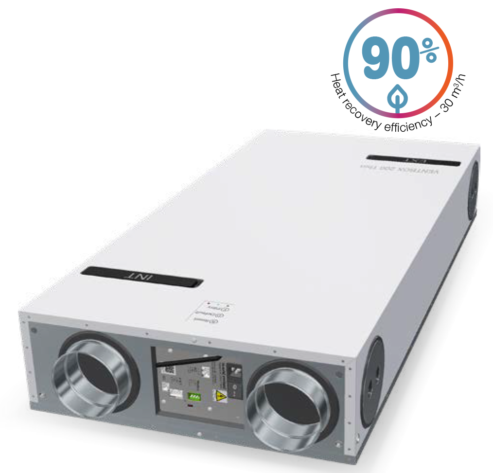
VENTBOX 200 Thin
Apartments and family houses up to 150 m²
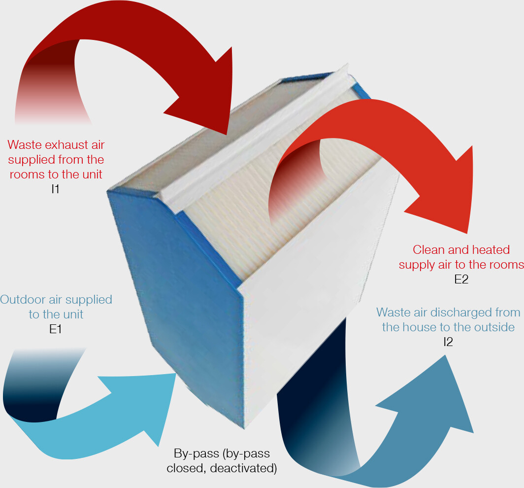
The VENTBOX 200 Thin ensures controlled ventilation with air recuperation, radon extraction, moisture removal in the house, and is also an effective tool for filtering dust and various allergens. At the same time, it helps reduce the thermal demands of the building. The basic principle of controlled ventilation is to bring fresh air into the house, which is heated through the walls of the recuperative exchanger by the exhaust air and then distributed to the living rooms. Conversely, the exhaust air is extracted from the bathrooms, toilets, and kitchen. In the exchanger, it transfers its heat and, together with water vapor, CO2, and other pollutants, is expelled through the facade out of the house.
-
Economy Version
It is designed for highly efficient operation, with optimization of production and operational parameters, allowing for top quality within economic affordability.
This variant offers an excellent price/performance ratio, making it the best choice for those who want to invest in a quality ventilation system with recuperation while staying within reasonable costs.
Very Quiet Operation
The VENTBOX 200 Thin Economy unit excels in acoustic properties. Its operation produces minimal noise, ensuring maximum comfort in living spaces.
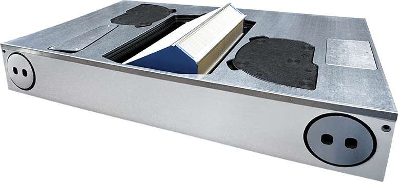
Compact Design
Thanks to its thoughtful dimensions, this unit is easily integrable even into limited spaces. Its very low installation height allows for installation in ceilings without compromising interior design.
Suitable for a Wide Range of Users
This unit is an ideal choice for a range of residential projects. Whether placed in an apartment, flat, or family house, it provides stable ventilation with maximum heat recuperation efficiency.
The VENTBOX 200 Thin Economy model will meet even the highest expectations at a reasonable price while maintaining high quality, efficiency, and functionality
-
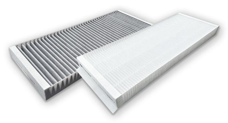
 Fresh air without allergens and pollen
 -
 On the wall or floor
 -
 Low consumption
| Recommended area | up to 150 m² |
| Energy class | A |
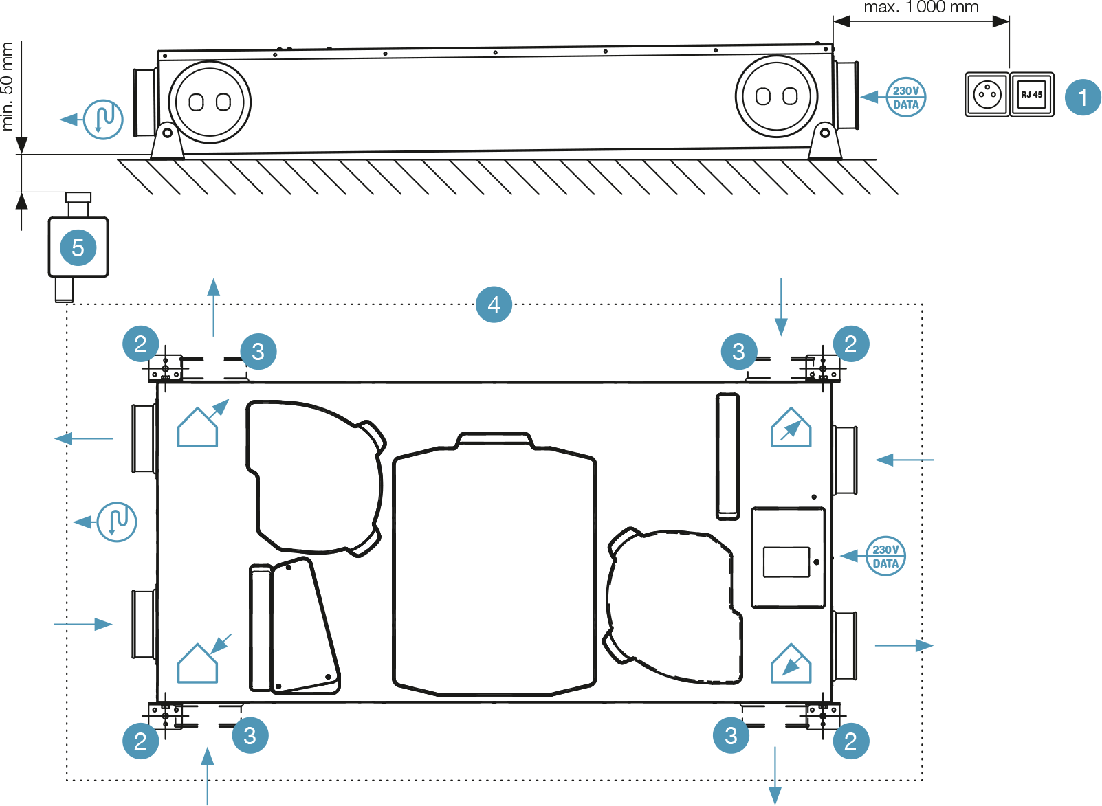
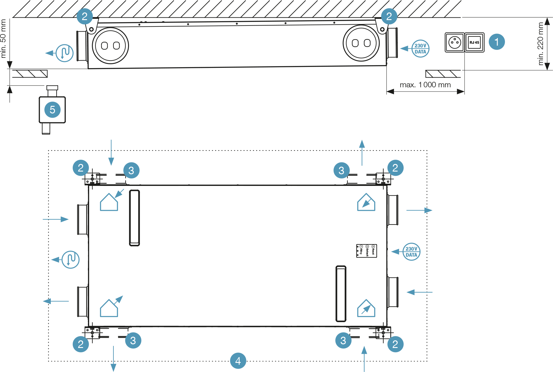
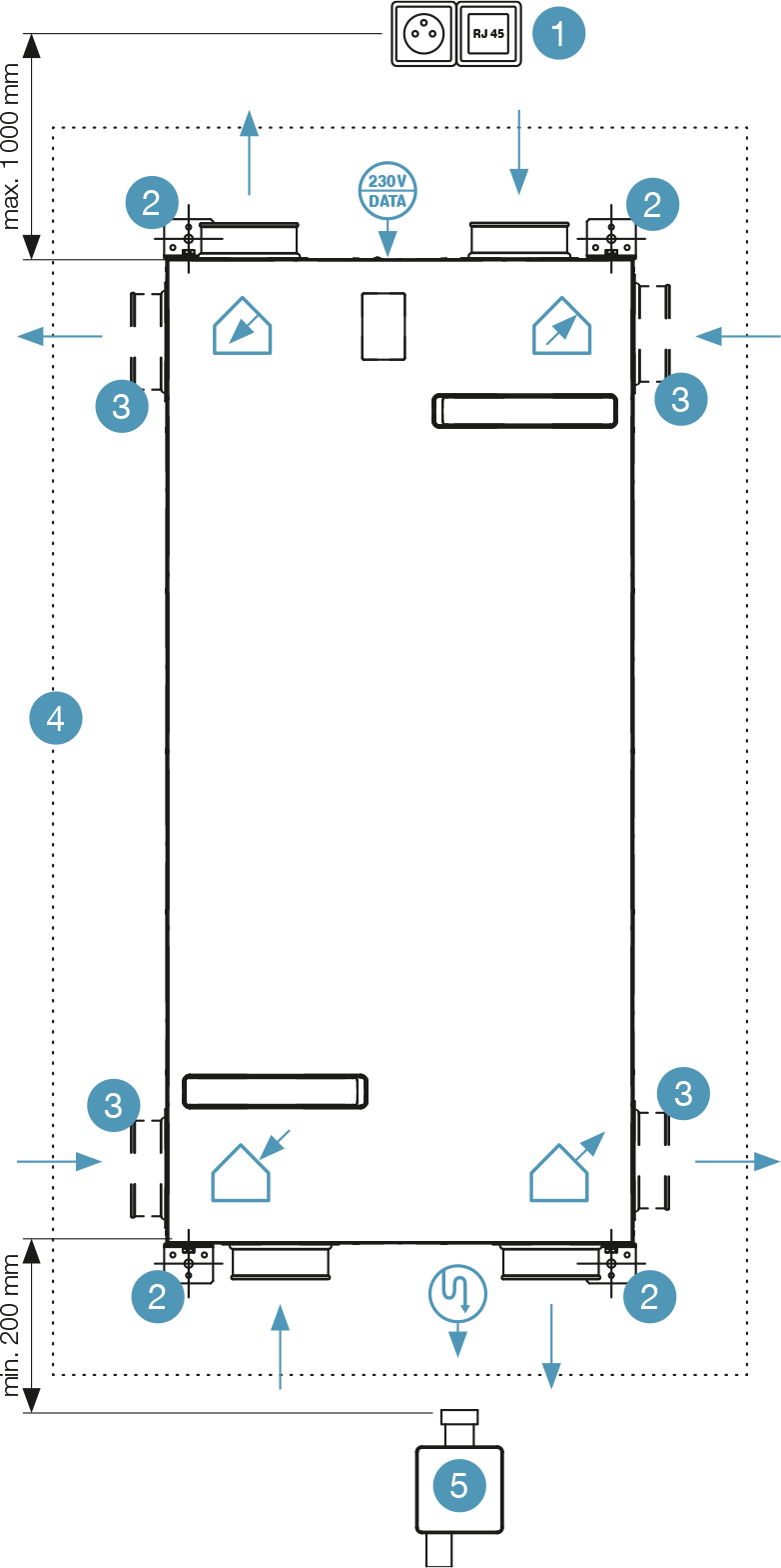
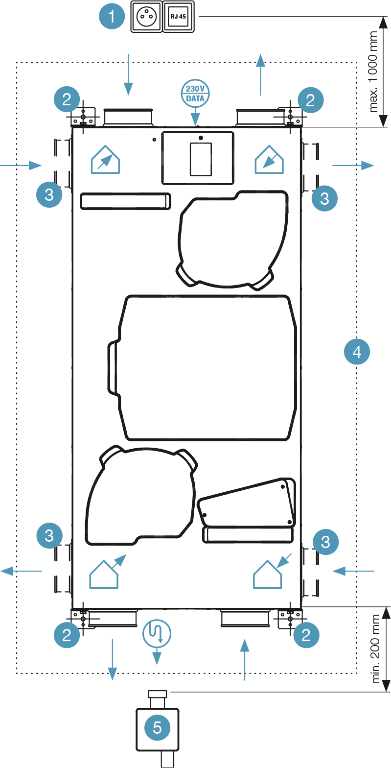
| Installation option | Floor mounting, under the ceiling, wall mounting / left or right variant |
| Dimensions (h × w × d) | 192 × 593 × 1 248 mm |
| Weight [kg] | 22,5 kg |
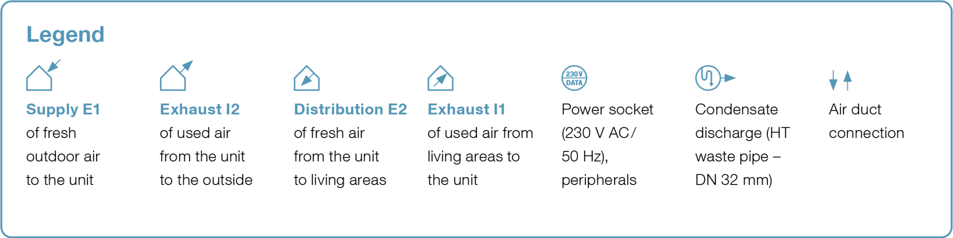
| Voltage | 230 V AC/50 Hz |
| Electric current without preheating [A] | 0,9 A |
| Electric current including preheating [A] | 5,8 A |
| Max. input power of the unit without preheating [W] | 119 W |
| Max. preheating input power [W] | 1 024 W |
| Total power input | 1 139 W |
| IP coverage | 30 |
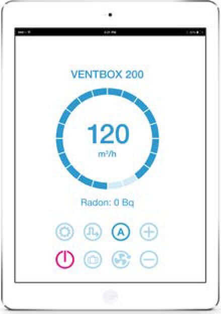
| Air flow [m³/h] | 50–225 m³/h |
| Maximum airflow in BOOST setting [m³/h] | 200 m³/h |
| Reference air flow [m³/h] | 140 m³/h |
| Displacement pressure [Pa] | 50–350 Pa |
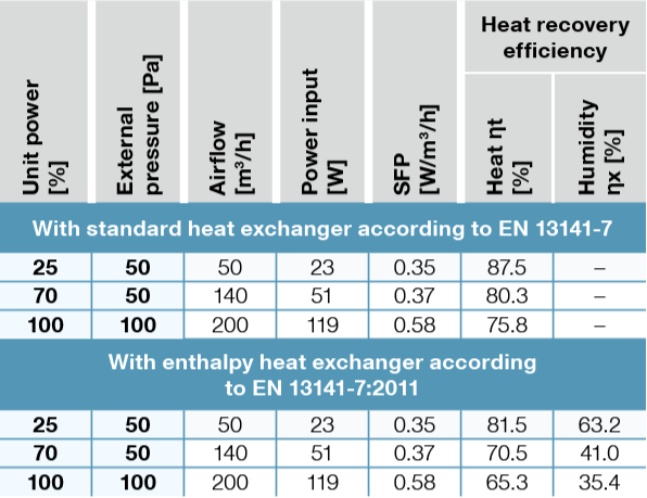
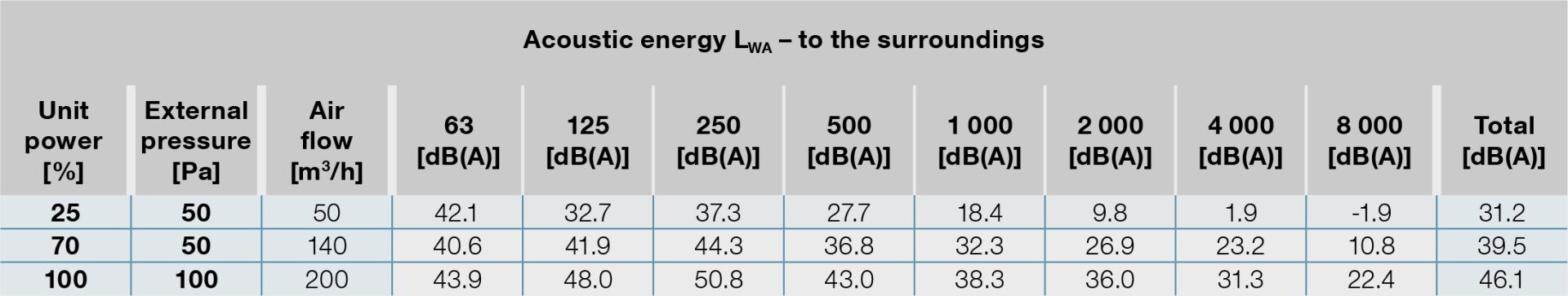
| Acoustic energy LWA [m³/h/Pa/dB] | 140 m³/h / 50 Pa / 39,5 dB |
| Heat transfer efficiency / Flow rate | 75,8 % / 200 m³/h; 80,8 % / 140 m³/h; 87,5 % / 50 m³/h |
| Electrical input (without preheating) | 119 W / 200 m³/h; 51 W / 140 m³/h; 23 W / 50 m³/h |
| ∅ of the connection necks [mm] | 125 mm |
| Type of pipe for condensate drainage | HT DN 32 mm |
| Specific power consumption SPI* W/m³/h | 0,37 W/at reference airflow 140 m³/h and disposition pressure of 50 Pa |
| Max. number of all sensors (CO2 / RH …) | 9 |
| Connector for fire sensor or EPS connection | Yes |
| Automatic frost protection | Yes |
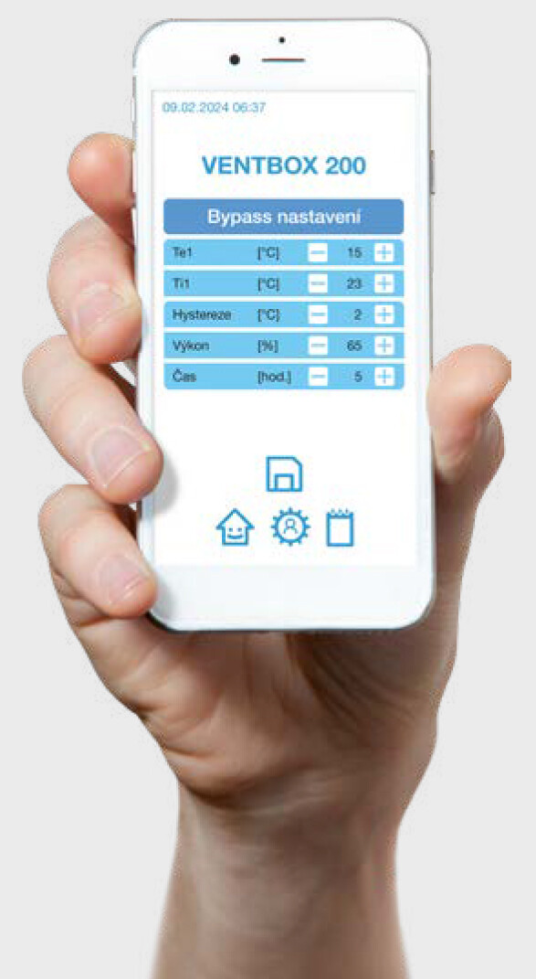
| Bypass function (exchanger bypass) | Yes |
| Shock ventilation | Yes |
| Weekly time mode | Yes |
| Measuring energy consumption | Yes |
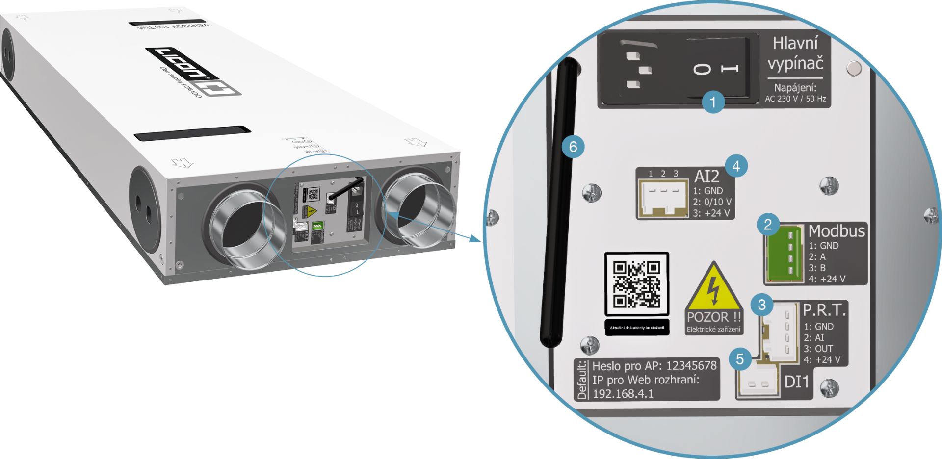
| Modbus TCP/IP communication | Yes |
| Modbus RTU communication | Yes |
| Analogue input | 2 |
| Digital input | 1 |
| Motors with constant flow function | Yes |
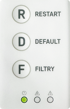
| Filter clogging indicator based on time interval | Yes |
| Filter clogging indicator based on filter pressure drop | No |
| Filters supply/exhaust (% of particles captured in a given filter class) | M5 ePM10 55 % (F7 optional) |
| By default, the unit is supplied with a counterflow heat exchanger (HRV) | |
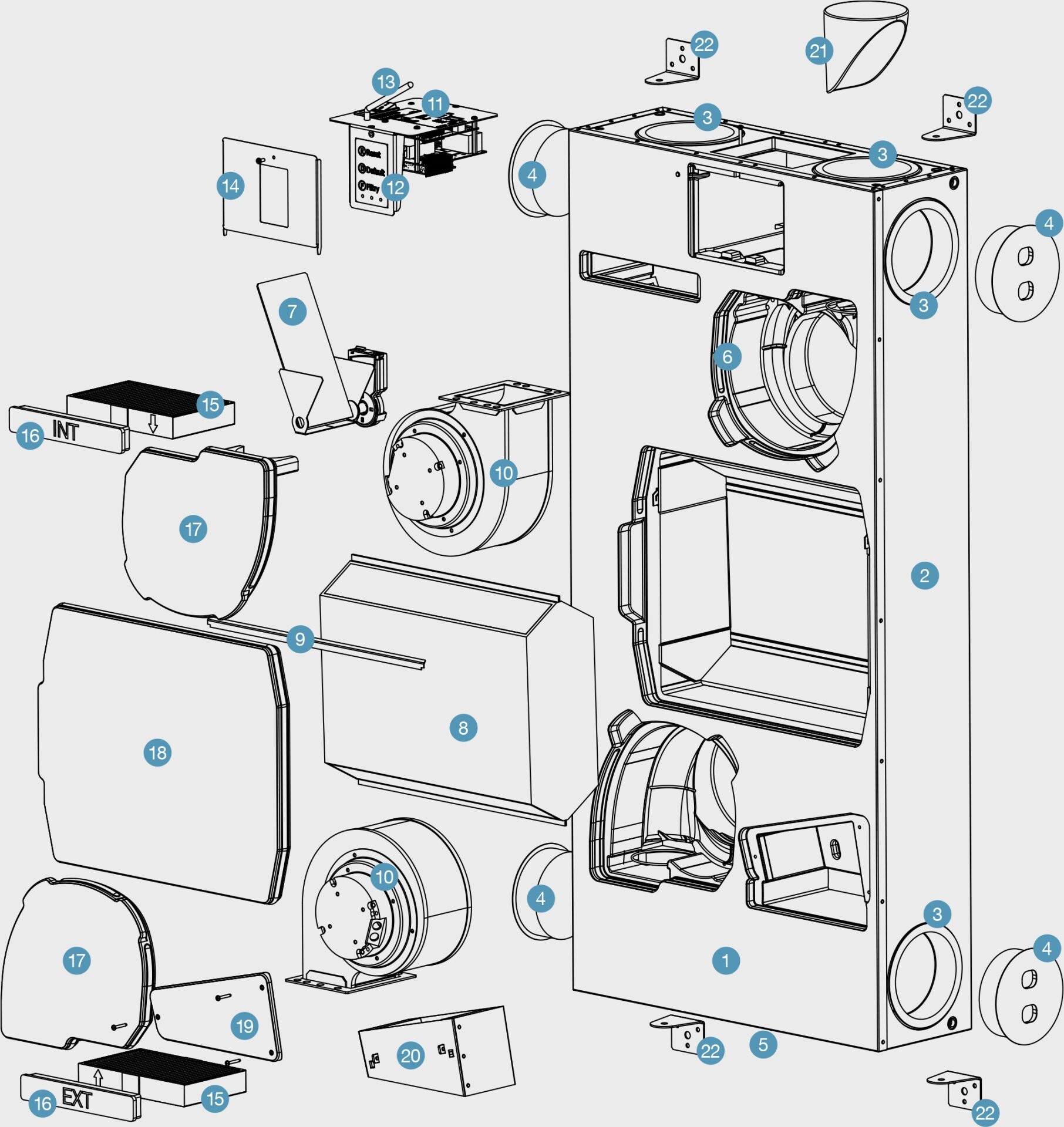
ORDERING CODES
Example of ordering code: VB1-0200-TC-EHR
VENTBOX 200 Thin first generation, with central heat recovery, standard EC fans version Optimum, standard heat exchanger with right-hand side connection.
| VENTBOX | Generation | | Volume flow | | Design | Heat recovery unit type | | Model / Type | Exchanger type | Connection option |
|---|---|---|---|---|---|---|---|---|---|---|
| V B | 1 | - | 0200 | - | T | C | - | E | H | R |
| | | | | | Thin | Centralized | | Economy | H - standard E - enthalpy | R - right L - left |
Contact us
For more information, do not hesitate to contact us